3 unit setting, 4 range setting, 5 setting damping time constant – Yokogawa Wireless Temperature Transmitter YTA510 User Manual
Page 13: 6 tag number and memo writing, Unit setting -6, Range setting -6, Setting damping time constant -6, Tag number and memo writing -6, A) changing the range with keypad
IM 01C50T03-01E
3-6
3. OPERATION
3.2.3
Unit Setting
B11: PV UNIT, B21: SV UNIT, B31: TV UNIT, B41: 4V
UNIT
Select the engineering unit for the process variables
assigned as PV, SV, TV, and 4V from degree C,
Kelvin, degree F* and degree R*. When mV or ohm is
specified as an input type, the unit is automatically set
to mV or ohms.
*:
Degree F and degree R are available only when
optional code /D2 is specified.
3.2.4
Range Setting
(a) Changing the range with keypad
Lower range value setting;
F10: LRV, Upper range value setting; F20: URV
The range for the PV corresponding to the 4 to 20mA
output signal is set at the factory before shipment. The
procedure to rerange is as follows.
F0304.EPS
DATA
DIAG
PRNT
ESC
PARAM
F10:LRV
0 degC
F20:URV
100 degC
F30:AUTO LRV
DISABLE
DEL
CLR
ESC
PARAM
F20:URV
0 degC
+ 150
1. Select F20: URV and press
[ENTER].
2. Input “150” and press [ENTER]
twice.
3. Press [OK].
Note : The unit selected in B11: PV UNIT is applied to the units used
for F10 and F20.
●
Example: Changing the measurement range from
0 to 100
°
C to 0 to 150
°
C .
NOTE
When entering numeric values at the range
setting, the value of URV must be greater than
that of LRV.
Range Setting Condition: URV > LRV
(b) Changing the range while applying an
actual input
F30: AUTO LRV
F35: AUTO URV
This feature allows the lower and upper range values to
be setup automatically with the actual input applied.
3.2.5
Setting Damping Time Constant
B12: PV DAMPING, B22: SV DAMPING,
B32: TV DAMPING, B42: 4V DAMPING
Setting the response time of each Process Variable to
make the output change very slowly with a rapid
change in input. Set the value from 0 to 99 seconds.
If the time constant is set to 2 seconds, the transmitter
calculates a reading every cycle using the damping
equation, in order to make the output 63 percent of the
input range after 2 seconds.
This damping time constant is normally set to work
when the temperature make a step change within 2
percent of the output range. The damping can be
changed using the “B13: PV DMP POINT” parameter.
●
Setting Damping Holding Point
B13: PV DMP POINT
This parameter is used to set the point where the
transmitter conducts the PV damping operation,
depending on a magnitude of the change in the
input value. When the change value in percent
exceeds the setting value, the transmitter outputs
the signal without the damping operation.
Set the value as a percent of span.
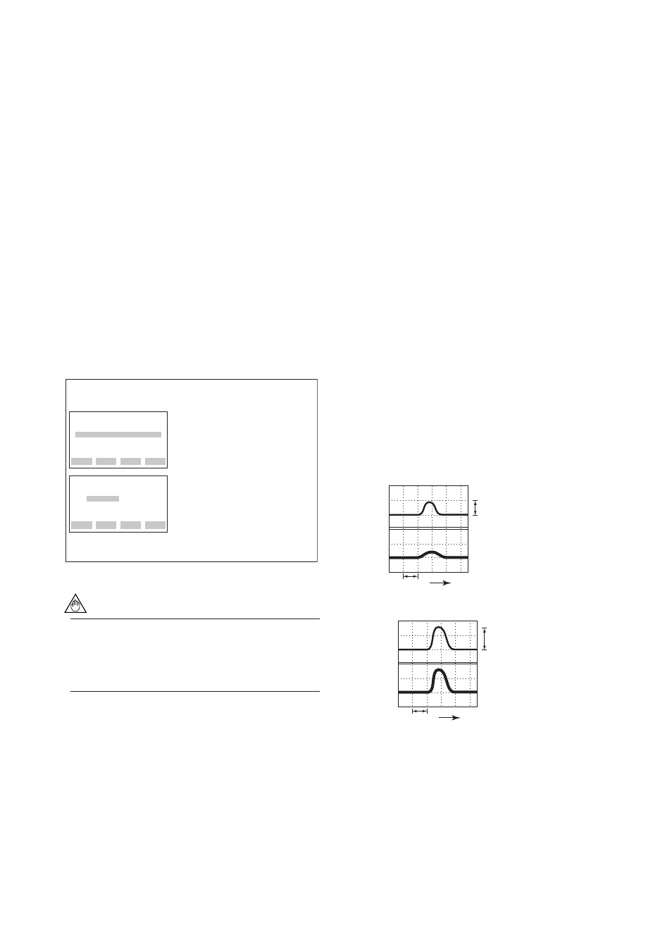
●
Example: Output pattern for the setting value of 10%
Input
Output
Time
3 sec.
9%
(
Њ
C)
10
0
(%)
10
0
Input
Output
Time
3 sec.
(
Њ
C)
10
0
(%)
10
0
14%
F0325.EPS
•Change value less then 10%
•Change value 10% or above
Assumed setting
Renge: 0 to 100
Њ
C
Damping time: 3 sec.
3.2.6
Tag Number and Memo Writing
Tag number
(See Appendix A. Section A.3.2)
C10: TAG NO.
Up to sixteen alphanumeric characters can be entered.
The tag number is as specified upon shipment.