Parameter summary, Parameter summary -1 – Yokogawa EJX440A User Manual
Page 33
IM 01C25T03-01E
5-1
5. PARAMETER SUMMARY
5.
PARAMETER SUMMARY
Instruments to which applicable:
F: Differential pressure transmitters
P: Absolute and gauge pressure transmitters
L: Flange mounted differential pressure transmitters
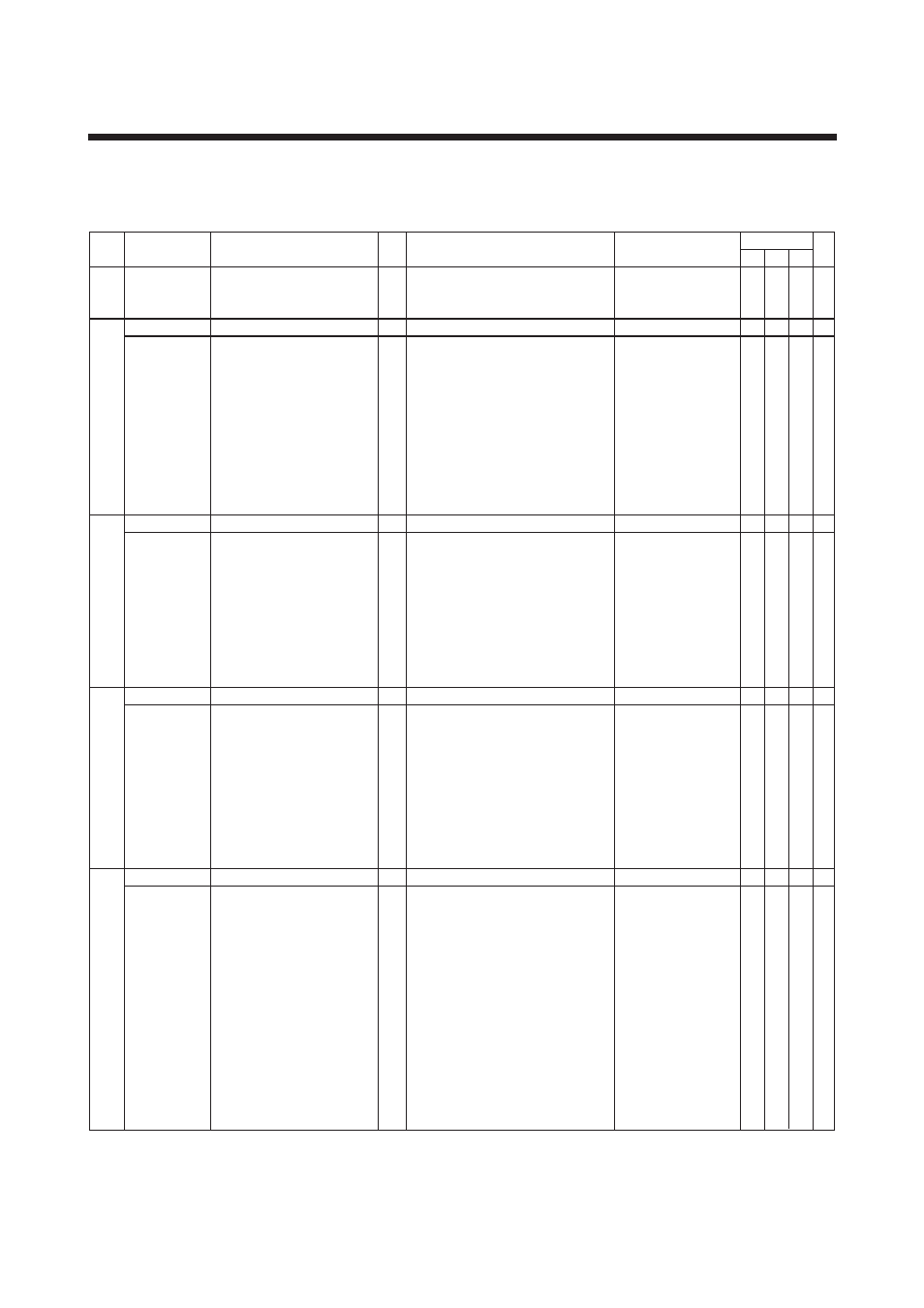
No.
Parameter name
Item
R/W
Content
Applicable model
Upload
data
F
P
L
Default value
01 MODEL
Model
R
02
TAG No.
Tag number
R
03 SELF
CHECK Self-diagnostics
R
A
DISPLAY
Measured data display
A10
OUTPUT
Output (in %)
R
Ϫ
2.5 to 110%
A11
PRES
Measured pressure after zero
R
Unit specified in C20
adjustment
A15
OUTPUT mA
Output current
R
3.6000 to 21.600 mA
A16
ENGR. OUTPUT User scaled value
R
Unit specified in I30
A17
ENGR. EXP
Exponents
R
Unit specified in I32
A20
SP %
Static pressure (in %)
R
Ϫ
10 to 110%
A21
SP
Static pressure after zero
R
Unit specified in D30
adjustment
A30
CAPSULE TEMP Capsule temperature
R
Unit specified in D40
A60
SELF CHECK
Self-diagnostics
R
Refer to Table 4.2 Alarm Message Summary
B
SENSOR TYPE
Sensor type
B10
MODEL
Model and capsule type
R
Model and capsule type
B11
STYLE NO.
Style number
R
Style number of product
B20
PRES LRL
Lower range limit
R
Unit specified in C20
B21
PRES URL
Upper range limit
R
Unit specified in C20
B22
P MIN SPAN
Minimum span
R
Unit specified in C20
B30
SP LRL
Lower range limit for static pressure
R
Unit specified in D30
B31
SP URL
Upper range limit for static pressure
R
Unit specified in D30
B32
SP MIN SPAN
Minimum span for static pressure
R
Unit specified in D30
B60
SELF CHECK
Self-diagnostics
R
See A60
C
BASIC SETUP
Setting data
C10
TAG NO.
Tag number
W
16 alphanumeric characters
C20
PRES UNIT
Measurement range unit
W
mmH2O, mmAq, mmWG, mmHg, Torr, kPa,
MPa, mbar, bar, gf/cm2, kgf/cm2, inH2O,
inHg, ftH2O, psi, atm, Pa, hPa
C21
PRES LRV
Lower range value
W
Ϫ
32000 to 32000 within measurement range
C22
PRES URV
Upper range value
W
Ϫ
32000 to 32000 within measurement range
C23
PRES POINT
Decimal place
W
0 to 4
C30
AMP DAMPING
Damping time constant at amplifier
W
0.50 (0.00) to 100.00 sec, see D50
C40
OUTPUT MODE Output mode
W
LINEAR or SUQARE ROOT
C60
SELF CHECK
Self-diagnostics
R
See A60
D
AUX SET 1
Auxiliary setting data 1
D10
LOW CUT
Low cut
W
0.00 to 20.00%
D11
LOW CUT MODE Low cut mode
W
LINEAR or ZERO
D15
H/L SWAP
Impulse piping accessing direction
W
NORMAL or REVERSE
D16
H2O UNIT SEL
H2O unit select
W
@4degC or @20degC (68.0F)
D20
OUT LIMIT (L)
Low side output limiter
W
Ϫ
2.50 to 110.00%
D21
OUT LIMIT (H)
High side output limiter
W
Ϫ
2.50 to 110.00%
D22
REV OUTPUT
Output reversal
W
NORMAL or REVERSE
D25
BURNOUT
CPU error
R
HIGH or LOW
D26
ERROR OUT
Hardware error
W
BURNOUT DIR or HOLD
D30
SP UNIT
Static pressure unit
W
See C20
D31
SP A/G SLCT
Gauge/Abs select for static pressure
W
GAUGE or ABSOLUTE
D32
ATM. PRESS
Coefficient for given gauge pressure
W
Unit specified in D30
D33
SP LRV
Lower limit of static pressure
W
Ϫ
32000 to 32000 within measurement range
D34
SP URV
Upper limit of static pressure
*
2
W
Ϫ
32000 to 32000 within measurement range
EJX
As specified
GOOD
As specified
kPa
As specified
As specified
2
2.00 sec or as specified
LINEAR or as specified
10.00%
LINEAR
NORMAL
@4degC
Ϫ
2.50%
110%
NORMAL
BURNOUT DIR
MPa
ABSOLUTE
0.10133 MPa
0.0 MPa
●
●
●
-
●
●
●
-
●
●
●
-
●
●
●
-
●
●
●
-
●
●
●
-
●
●
●
-
●
●
●
-
●
-
●
-
●
-
●
-
●
●
●
-
●
●
●
-
●
●
●
-
●
●
●
-
●
●
●
-
●
●
●
-
●
●
●
-
●
-
●
-
●
-
●
-
●
-
●
-
●
●
●
-
●
●
●
●
●
●
●
●
●
●
●
●
●
●
●
●
●
●
●
●
●
●
●
●
●
●
●
●
●
●
●
-
●
●
●
●
●
●
●
●
●
-
●
●
●
●
●
●
●
●
●
●
●
●
●
●
●
●
●
●
●
●
●
-
●
●
●
●
●
-
●
●
●
-
●
●
●
-
●
●
●
-
●
●
●
-
●
●
*
1: R/W: R = Read only, W = Read & Write
*
2: The default value shows MWP (Maximum working pressure) of the capsule.
Since the working pressure limit varies according to the Model, refer to the General Specifications section in each user’s manual.
*
1