Yokogawa EJX440A User Manual
Page 23
IM 01C25T03-01E
3-15
3. OPERATION
When using BT200, the output signal can be adjusted
either in % or pressure unit. The unit can be selected
by the parameter J09: ADJ UNIT. Output signal can be
changed by displaying parameter A10: OUTPUT for %
or J10: OUTPUT for pressure unit.
This section discribes the zero adjustment procedure by
using the pressure unit.
a-1. Zeroing
Setting the parameter of J11: P ZERO ADJ carries out
the zero adjustment and automatically sets the applied
“0” input values to the transmitter’s output value of
zero, keeping the span constant. Use this setting when
the LRV is known to be 0 kPa.
FEED
NO
OK
SET
J11:P ZERO ADJ
0.00000 kPa
CLR
DEL
ESC
SET
J11:P ZERO ADJ
0.00000 kPa
+ 0
A pressure of 0 kPa is applied.
Press the key twice
after the pressure has become
stable.
Zero adjustment is completed.
Press the (OK) key.
F0331.EPS
Transmitter measures pressure of
0.03585 kPa.
Transmitter measures pressure of
0.00000 kPa.
A11:PRES
0.03585 kPa
A11:PRES
0.00000 kPa
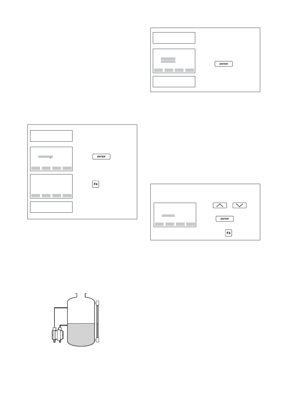
a-2. Level Adjustment
The zero adjustment by the parameter of J11: P ZERO
ADJ calibrates the transmitter output corresponding to
the actual tank level. To perform this adjustment, first
use a glass gauge or the like to determine the actual
tank level, then enter the correct data as shown below.
F0332.EPS
25.00 kPa
0.00 kPa
Actual level
13.50 kPa
DPharp span:
0 to 25.00 kPa
Actual level:
13.50 kPa
Transmitter output: 13.83 kPa
DPharp
CLR
DEL
ESC
SET
J11:P ZERO ADJ
0.00000 kPa
+ 045.0
+ 13.5
Enter the present actual level,
13.5 kPa.
Press the key twice.
The measured pressure is changed
to 13.5 kPa.
F0333.EPS
Transmitter measures present
pressure of 13.83 kPa.
A11:PRES
13.83 kPa
A11:PRES
13.5000 kPa
a-3. Using External Zero-adjustment Screw
This method permits zero adjustment without the
BT200. Use a slotted screwdriver to turn the zero-
adjustment screw. See the hardware manual for details.
Note that the parameter of J55: EXT ZERO ADJ must
be
ENABLE
to perform this adjustment.
Follow the procedure below to enable or inhibit zero
point adjustment from the zero-adjustment screw on
the transmitter.
This is set to
ENABLE
when the instrument is
shipped.
• Example: Inhibiting zero adjustment by the
external zero-adjustment screw.
ESC
SET
J55:EXT ZERO ADJ
ENABLE
< ENABLE >
< INHIBIT>
Use the or key to
select INHIBIT.
Press the key twice to
enter the setting.
F0335.EPS
Then press the (OK) key.
b. Full Sensor Trim
(J11: P ZERO ADJ, J12: P SPAN ADJ,
J15: P ZERO DEV, J16: P SPAN DEV)
Full sensor trim is carried out with a series of the
procedure of J11: P ZERO ADJ and J12: P SPAN
ADJ. Also, you can manually perform the trimming
procedure by using J15: P ZERO DEV and J16: P
SPAN DEV.
The full sensor trim is a two-point adjustment, and the
lower point adjustment should always be performed
before the upper point adjustment in order to maintain
the pitch between the zero and 100% points within the
calibration range.
In the manual method, the reference pressure should
also be applied to the transmitter at both lower and
upper point of trim ends. Without the reference
pressure, J15: P ZERO DEV and J16: P SPAN DEV
may not represent the correct value of adjustment point
for each.