6) integral indicator scale setup, 6) integral indicator scale setup -9, See (a.) through (d.) for each setting procedure – Yokogawa EJX440A User Manual
Page 17
IM 01C25T03-01E
3-9
3. OPERATION
The low cut point has hysteresis so that the output
around the point is behaved as below figure.
Output mode: Linear
Low cut mode: Zero
Low cut: 20.00%
F0317-02.EPS
Setting range: 0 to 20%
2%
2%
4mA
Output
Low cut point
Input
Hysteresis
fixed at 10%
of the cut point
7.2mA
(20%)
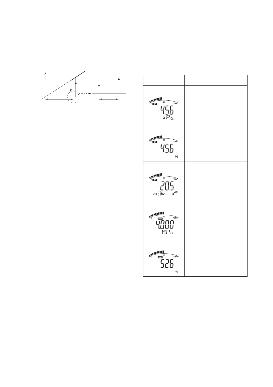
(6) Integral Indicator Scale Setup
The following five displays are available for integral
indicators: input pressure*
1
, % of range, user set scale,
input static pressure, and % of static pressure range*
1
.
A cycle of up to four displays can be shown by
assigning variables to the parameters I10 to I13: DISP
OUT1 to DISP OUT4.
T0306.EPS
Available displays
Input pressure
(PRES)
% of range
(PRES %)
User set scale
(ENGR. PRES)
Input static pressure
(SP)*
1
% of static pressure range
(SP %)*
1
Indicates values of input pressure
with the indication limits
Ϫ
32000 to
32000.
Indicates input pressure in
Ϫ
2.5 to
110% range depending on the
measuring range (C21, C22).
Indicates values depending on the
engineering range (I33, I34) with the
unit (I30).
Indicates input static pressure with
the indication limits –32000 to 32000.
Reference pressure is factory-set in
absolute.
Indicates input static pressure in –10
to 110% range depending on the
measuring range (D33, D34).
A11:PRES
456 kPa
Description
and related parameters
A10:OUTPUT
45.6 %
A16:ENGR.OUTPUT
20.5 m3/min
A17:ENGR.EXP
ϫ100
A21:SP
4.000 MPa
A20:SP %
52.6 %
*
1: Available for differential pressure transmitter.
See (a.) through (d.) for each setting procedure.