Error codes, Error code messages, 25 error code messages – Watlow Series 965 User Manual
Page 25: Error code messages ç
Tuning and Operating, Chapter 5
WATLOW Series 965 User's Manual
25
Error Codes
Alarm Silencing is available with the deviation alarm. When SIL is selected as
"on," the operator must manually disable the alarm by pressing the A/M key
once on initial power up (in either the latching or non-latching mode). Alarm
silencing disables the alarm output relay. However, the L2 LED (also the lower
display when Ot2 = dEA) shows an alarm condition until the process value is
within the "safe" region of the deviation alarm band. Once the process value
crosses into the "safe" region, both a latching or a non-latching alarm is ready.
Any future deviation outside this safe band triggers an alarm.
NOTE
:
An alarm display will
be masked by an
error condition or
when the control is
in the Calibration or
Setup Menus.
ç
CAUTION:
Electrical noise or a
noise event, vibra-
tion or excess
environmental
moisture or tem-
perature may cause
Series 965 errors to
occur. If the cause
of an error is not
otherwise apparent,
check for these.
Error Code Messages
ç
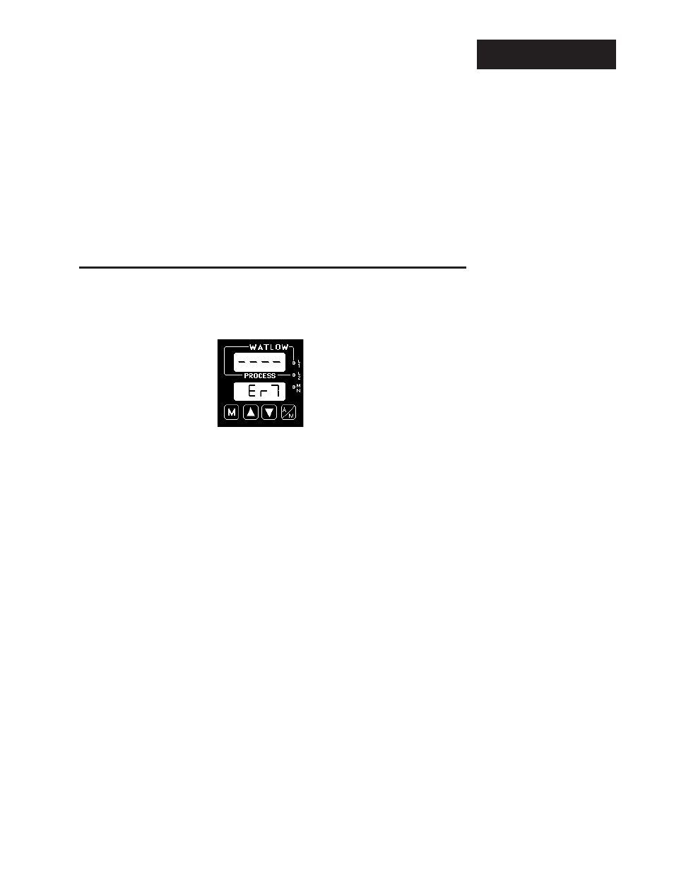
Four dashes, "- - - -", in the upper display indicate a Series 965 error. The error
code is visible in the lower display.
Er 2
- Sensor underrange error (only applies to RTD units)
The sensor input generated a value lower than the allowable signal range, or the
A/D circuitry malfunctioned. Enter a valid input. Make sure the In parameter
(selected in the Setup menu) and the DIP switch settings both match your
sensor. Refer to the table below for the appropriate input type and range.
Er 4
- Configuration error
The unit's microprocessor is faulty; call the factory.
Er 5
- Non volatile checksum error
The nonvolatile memory checksum discovered a checksum error. Unless a
momentary power interruption occurred while the unit was storing data, the
nonvolatile memory is bad. Call the factory.
Er 6
- A/D underflow error
The A/D circuit is underrange. An open or reversed polarity sensor is the most
likely cause. Check the sensor; if the connection is good and functions properly,
call the factory. The A/D underrange voltage is too low to convert an A/D signal.
Make sure the In parameter matches your sensor and DIP switches are set
accordingly.
Er 7
- A/D overflow error
The A/D circuit is overrange. An open or reversed polarity sensor is the most
likely cause. Check the sensor; if the connection is good, and the sensor
functions properly, call the factory. The A/D overrange voltage is too high to
convert an A/D signal. Make sure the In parameter matches your sensor and
DIP switches are set accordingly.