Proface APL3000B - Node Box PC User Manual
Page 49
PS-3450A Series Hardware Manual
2-26
Switches
The following switch settings corresponding to each Serial Interface need to be signified. The switches are on
the PS-A’s circuit board.
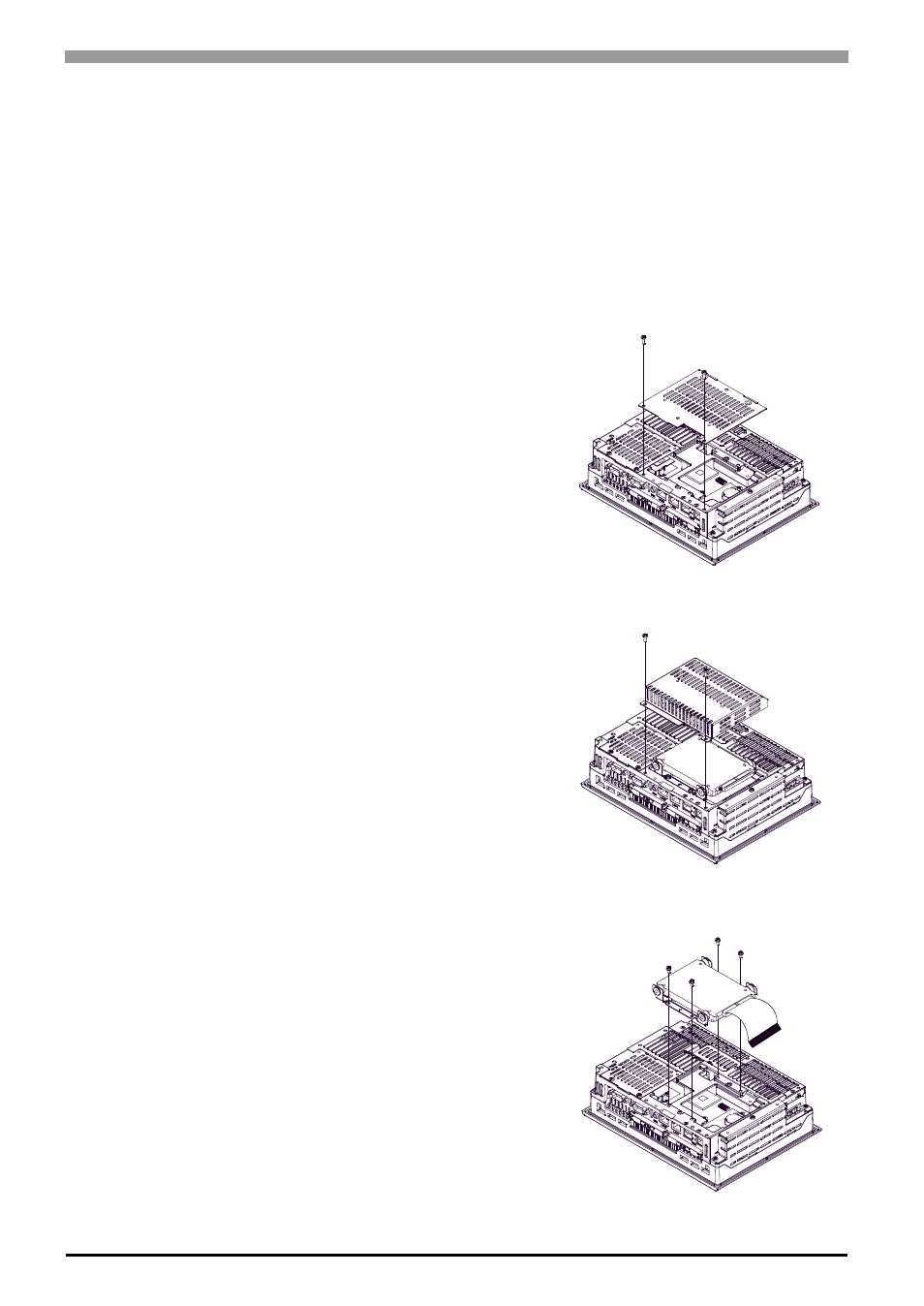
• To change the switch settings
The switches are on the PS-A’s circuit board. First of all, remove the cover.
Unscrew the screws (2) of the IDE cover and remove the IDE
cover. When replacing the cover, the torque required for these
screws is 0.5 to 0.6N
•m.
(1)
Unscrew the screws (2) of the HDD cover and remove
the HDD cover. When replacing the cover, the torque
required for these screws is 0.5 to 0.6N
•m.
(2)
Unscrew the screws (4) of the HDD unit, remove the
cable connector from IDE I/F while lifting up the HDD
unit, and remove it.
To replace the HDD unit, connect the cable connector to
IDE I/F securely and fix the HDD unit with the screws
(4). (For the location of the IDE/IF, refer to the follow-
ing figure "Inside of the rear".) The torque required for
these screws is 0.5 to 0.6N
•m.