20ms, 5input derating, Input circuit – Proface LT3300 - 5.7 All-in-One HMI" User Manual
Page 5
5
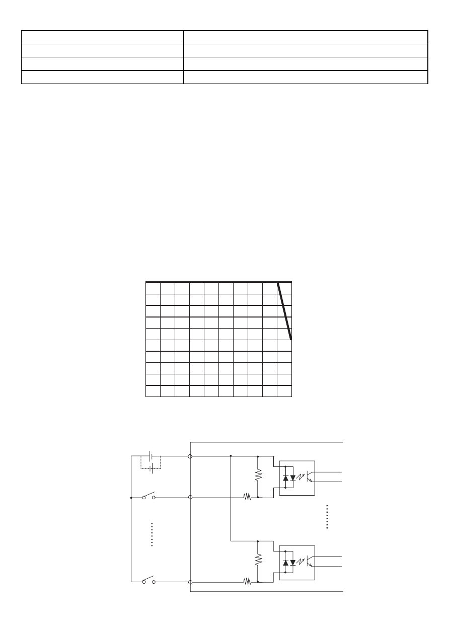
Input Derating
Using LT input voltage that exceeds the rated voltage, the input ON voltage, the number of input
points or the LT’s temperature can effect. Also, the LT's input section could overheat, which
could lead to an accident or malfunction. Refer to the following drawing and perform Input
Derating within the LT unit’s rated range.
Input Circuit
Status Display
None
Isolation Method
Photocoupler Isolation
External Connection
22-pin connector (used with Output section)
External Power Supply
For Signal: DC 24V
*1 In the case of IN0, IN2, IN4, and IN6, the input delay time generates a 5µs delay.
For example, in the case of a 0.5ms-cycle sampling:
5µs (ON to OFF) + 0.5ms (sampling cycle) + 5µs (OFF to ON) = 0.51ms
A minimum 0.51ms-restriction is imposed on the input pulse width.
In the case of IN1, IN3, IN5, and from IN7 to IN11, the input delay time generates a 0.5ms-delay. For
example, in the case of a 0.5ms-cycle sampling:
0.5ms (ON to OFF) + 0.5ms (sampling cycle) + 0.5ms (OFF to ON) = 1.5ms
A minimum 1.5ms-restriction is imposed on the input-pulse width.
*2 Digital filter can be set at intervals of 0.5 ms.
(%)
100
50
0
0
10
20
30
40
50 (
°C)
Input ON
Rat
e
Ambient Operating Temperature
DC24.0 to DC26.4V
DC28.8V
DC 24V
External Power
Internal Circuit
Internal Circuit
COM B7
+
-
IN11 A6
- +
*1
*1 Dotted line shows
connection to sink
output type.
IN10 B6
IN9 A5
IN8 B5
IN7 A4
IN6 B4
IN5 A3
IN4 B3
IN3 A2
IN2 B2
IN1 A1
IN0 B1