Dimensions 1 installation 2, Direct panel installation, Din rail installation – Proface LT3200 - 3.8 All-in-One HMI" User Manual
Page 3: Unit: mm [in.] unit: mm[in.] unit: mm [in, Installation removal 100
-3-
A B L D R M 0 3 0 2 4
72mm[2.83]
100mm[3.94]
60mm[2.36]
70mm[2.76]
59.5mm[2.34]
55mm[2.17]
27.5mm
[1.08]
35mm
[1.38]
90mm[3.54]
110mm[4.33]
44mm[1.73]
15mm[0.59]
27.5mm
[1.08]
V Out
N
L
+ +
Input
10 0 - 240VAC
Out put
24VDC -1.3A
1
1
2
A B L D R M 0 3 0 2 4
V Out
N
L
+ +
Input
10 0 - 240VAC
Out put
24VDC -1.3A
1
2
1
2
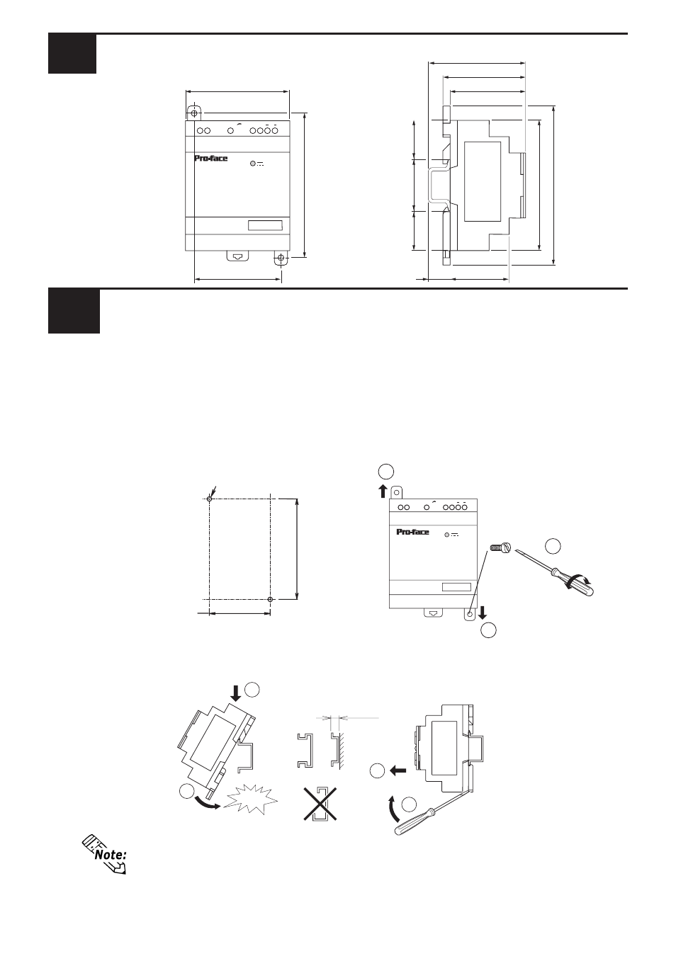
Dimensions
1
Installation
2
Direct Panel Installation
Create two attachment screw holes using the dimensions shown below, and posi-
tion this product so that its product attachment tabs (Top and bottom) align with
the attachment screw holes. Secure the product in place using M4 attachment
screws, using a torque of 1 N•m. For the efficient use of the ABL-DRM03024,be
sure to install this product as shown below.
DIN Rail Installation
Confirm that the DIN rail fastener hook is clipped in place and the module is held securely.
Installation
Removal
100
+0.2
-0.2
[3.94 ]
+0.01
-0.01
When attaching the ABL-DRM03024 to a panel, extend the product’s attach-
ment tabs. When attaching the ABL-DRM03024 to a DIN rail, retract the
product’s attachment tabs.
snap
M4
× 20
2-M4
7.5[0.30]or more
[2.36 ]
+0.01
-0.01
60
+0.2
-0.2
Unit: mm [in.]
Unit: mm[in.]
Unit: mm [in.]