External interfaces, Serial interface – Proface GP4100 - 3.4 Compact HMIs" User Manual
Page 3
3
External Interfaces
• For instructions on how to connect to other
devices, always refer to the "GP-Pro EX Device/
PLC Connection Manual".
1.
Serial Interface
• For detailed information on pins, refer to the GP-
4100 Series Hardware Manual.
• The serial interface of the RS-232C and RS-422/
485 types is not isolated. Always connect pin #5
SG (Signal Ground) to the connected device,
especially if the connected device is also not
isolated. Failure to do so may damage the RS-
232C/RS-422/RS-485 circuit.
• An SG (Signal Ground) and FG (Frame Ground)
are connected internally in the RS-232C and RS-
422/485 types. When connecting an external
device to the GP using the SG terminal, be sure
to check that no short-circuit loop is created when
you setup the system.
RS-232C and RS-422/485 Types
Included COM I/F connector
(9-pin, 2-piece terminal block)
• A termination resistor can be set using the DIP
Switch (4-bit) on the rear of the RS-422/485 type.
Factory default settings are all set to “OFF” (no
termination resistor). Check the termination
resistor required for connection to the connected
device (PLC) and install if necessary. For detailed
information, refer to the GP-Pro EX Device/PLC
Connection Manual.
Communications Cable Specifications
Wiring the COM Interface Connector
• Always ensure that the connector has been
removed from the GP unit before wiring the con-
nector. Failure to do so may result in electric
shock.
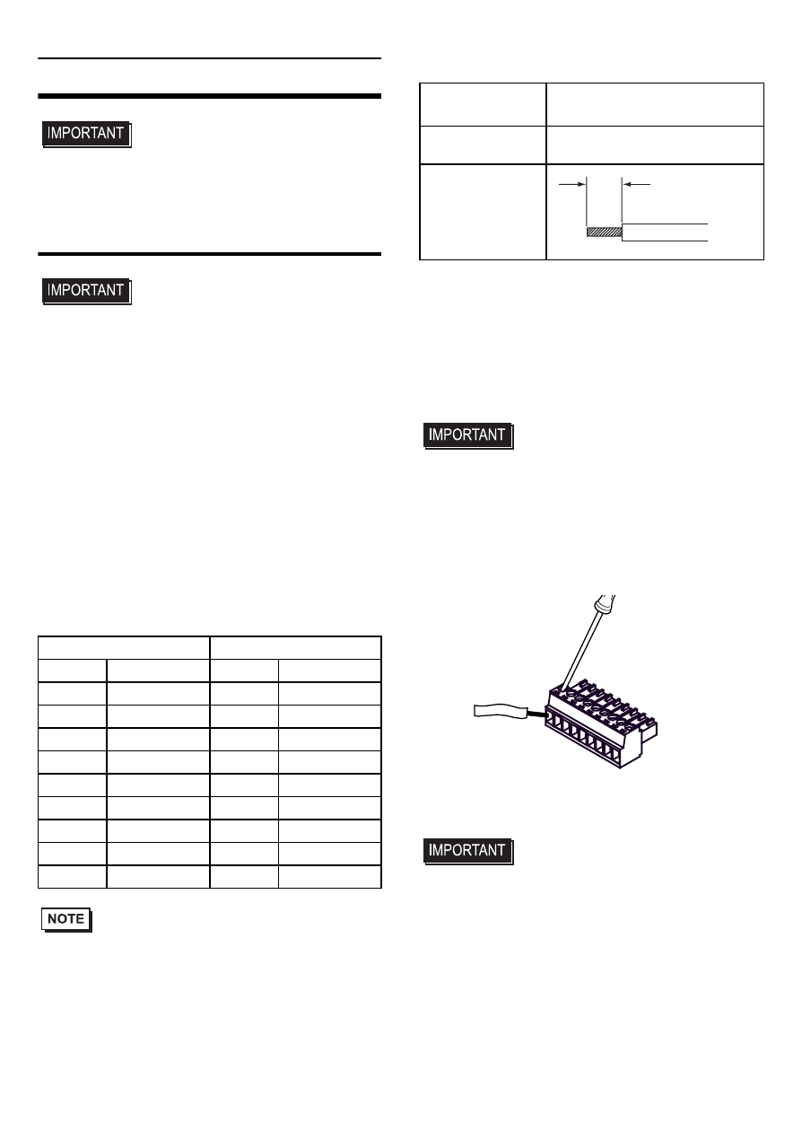
(1) Use a flat-blade screwdriver (Size 0.4 X 2.5) to
loosen the terminal screws.
(2) Strip the communications cable, and attach it to
the terminal connector.
(3) Use a flat-blade screwdriver to tighten the
appropriate terminal screws on the terminal
connector from step 2.
• The torque required to tighten these screws is
0.196N
•m (1.735[Lb•in]).
(4) Insert the connector into the GP unit’s serial
interface.
RS-232C type
RS-422/485 type
Label
Signal Name
Label
Signal Name
CI
CI(RI)
CSB
CSB
CD
CD
CSA
CSA
CS
CS(CTS)
ERB
ERB
RS
RS(RTS)
ERA
ERA
SG
SG
SG
SG
DR
DR(DSR)
RDB
RDB
ER
ER(DTR)
RDA
RDA
RD
RD(RXD)
SDB
SDB
SD
SD(TXD)
SDA
SDA
Communications
Cable Diameter
*1
*1
When inserting two wires into one terminal con-
nector, the simple wire diameter is 0.08 to
0.5mm
2
(28 - 22 AWG), and the stranded wire di-
ameter is 0.08 to 0.75mm
2
(28 - 20 AWG).
0.14 to 1.5mm
2
(28 - 16 AWG)
Conductor Type Simple or Stranded Wire
*2
*2
If the Conductor’s end (individual) wires are not
twisted correctly, the end wires may either short
against each other, or against an electrode.
Conductor
Length
7mm
[0.28in]
(2)
Insert the wire into the
terminal connector.
Terminal
Connector
(1)
Use a flat-blade
screwdriver to
loosen the terminal
screws.
(3)
Use a flat-blade
screwdriver to tighten
the terminal screws.