Ex module connecting diagram – Proface AGP3500 - 10.4 DIO HMI" User Manual
Page 5
5
1.
Arrangement of the HTB’s power cable and the I/O cables
Power Cord Specifications
Power Cord
1 mm
2
to 1.5mm
2
(AWG 18 and AWG
16). Use the shortest wire length
possible. The grounding wire should
be 1.50 mm
2
(AWG 16).
I/O cables
0.20 mm
2
to 1.31 mm
2
, (AWG 24 to
AWG 16).
(accepts up to two wires fitted with
cable ends or tags)
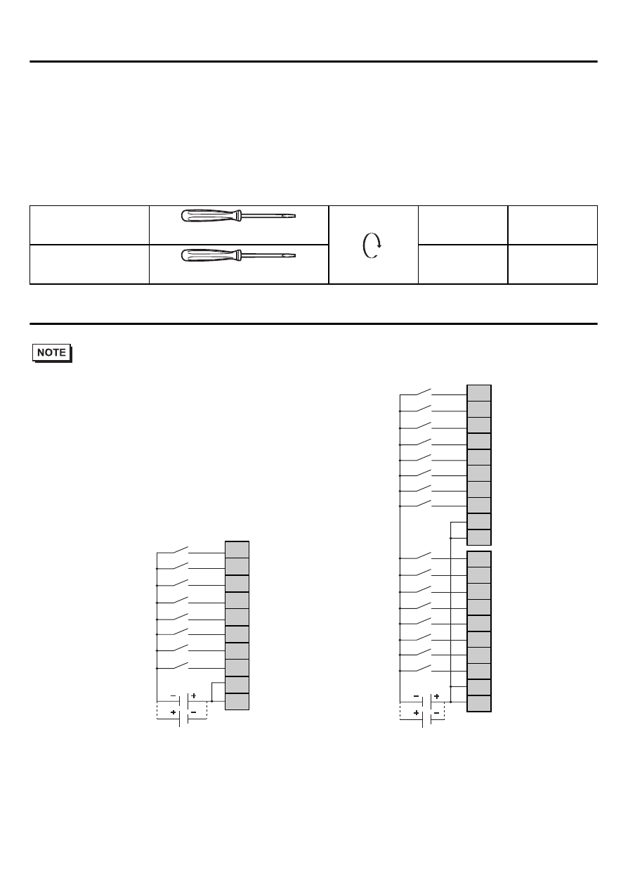
2.
EX module connecting diagram
• Please install an applicable fuse to prevent an overload in the circuit, if necessary.
Power supply
section
Ø 3.5 mm [0.14 in.]
C
N·m
0.6
In/Output terminal
connector
Ø 2.5 mm [0.10 in.]
N·m
0.4
(1) Source input
(2) Sink input
(1)
(2)
(1)
(2)
(1) Source input
(2) Sink input
*1 The terminals are
connected together
internally.
*1
*1
0
1
2
3
4
5
6
7
COM
COM
0
1
2
3
4
5
6
7
COM
COM
8
9
10
11
12
13
14
15
COM
COM
This manual is related to the following products:
- AGP3400 - 7.5 DIO HMI" AGP3300 - 5.7 DIO HMI" AGP3600 - 12.1 FLEX Network HMIs" AGP3500 - 10.4 FLEX Network HMI" AGP3400 - 7.5 FLEX Network HMI" AGP3600 - 12.1 CANopen HMI" AGP3500 - 10.4 CANopen HMI" AGP3400 - 7.5 CANOpen HMI" AGP3300 - 5.7 CANopen HMI" LT3200 - 3.8 All-in-One HMI" AGP3300H - 5.7 Handheld HMIs" AGP3750 - 15 Multi-Media HMI" AGP3650 - 12.1 Multi-Media HMIs" AGP3550 - 10.4 Multi-Media HMIs" AGP3450 - 7.5 Multi-Media HMI" AGP3360 - 5.7 Multi-Media HMI" AST3300 - 5.7 Basic HMI" AST3200 - 3.8 Basic HMI" AGP3600 - 12.1 Standard HMIs" AGP3500 - 10.4 Standard HMIs" AGP3400 - 7.5 Standard HMI" AGP3300 - 5.7 Standard HMI" AGP3200 - 3.8 Standard HMI"