Maple Systems OMI5100A-CE User Manual
Page 9
9
OMI5000 Series Installation Guide
1010-1013 Rev 01 www.maplesystems.com
P/N 6030-0009 by the foot from Maple Systems to make your own
power cable.
Always run the DC ground wire directly back to the signal return of the
power supply. Do not use the chassis ground wire as your signal return.
Caution: To prevent possible damage to the OMI, we
recommend waiting ten seconds after removing power to the
OMI before applying power again.
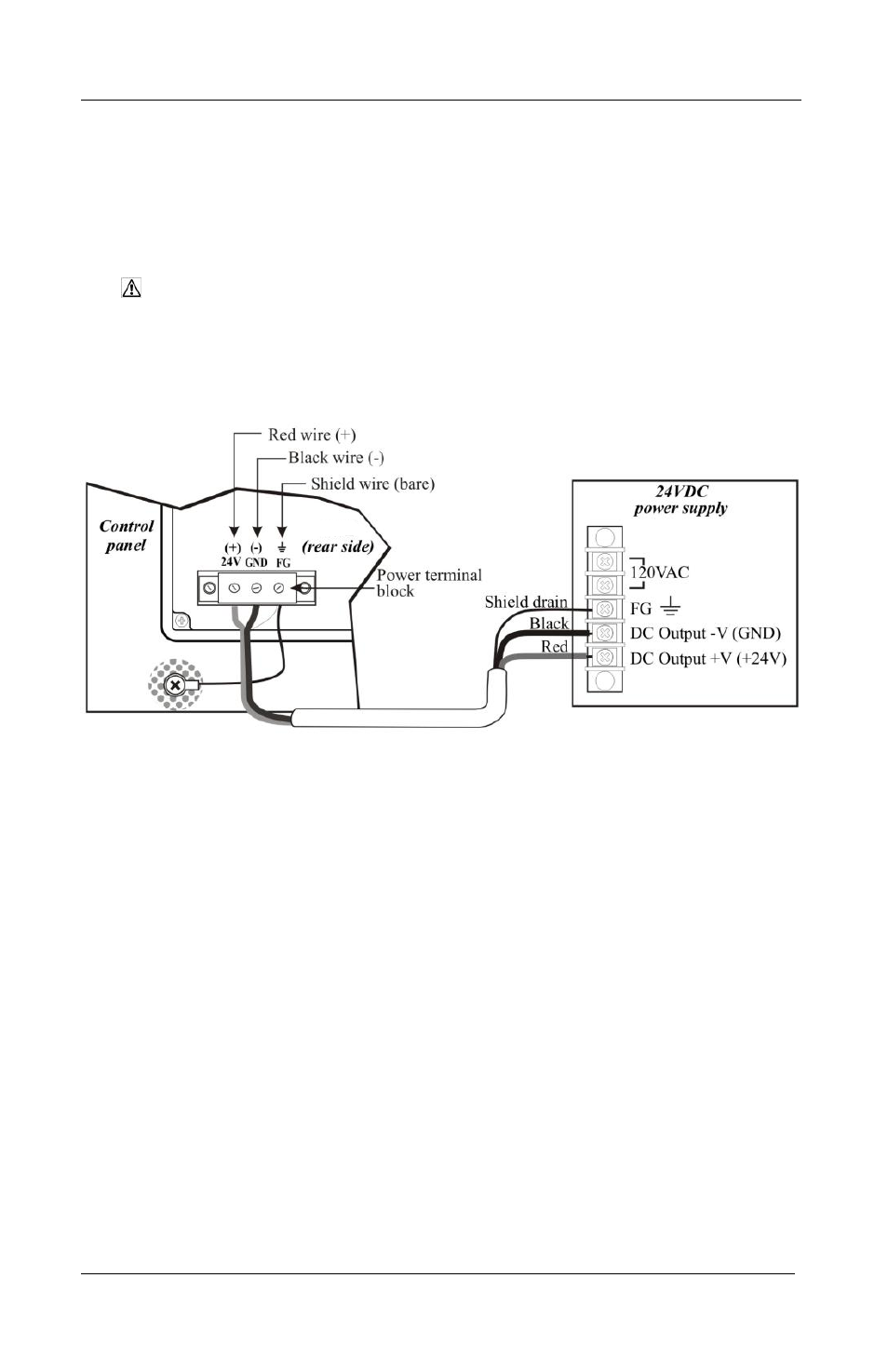
Figure 4: OMI Power Wiring
To connect the OMI to power:
1. Connect the power cable to the OMI.
a. Strip the power cable shield to expose 2” of the black and
red wires.
b. Strip about ¼” of insulation from the black and red wires.
c. Connect the red wire to the 24V DC positive (+) input of the
OMI power terminal block.
d. Connect the black wire to the 24V DC negative (–) input of
the OMI power terminal block.
e. Connect the power cable shield wire to the OMI power
terminal block’s chassis ground input.