Maintenance, Caution, Gun tubes and nozzles – Lincoln Electric IM10071 MAGNUM PRO THRU THE ARM ROBOTIC TORCH User Manual
Page 22: Cable cleaning
D-1
MAINTENANCE
D-1
MAGNUM® PRO THRU THE ARM ROBOTIC TORCH
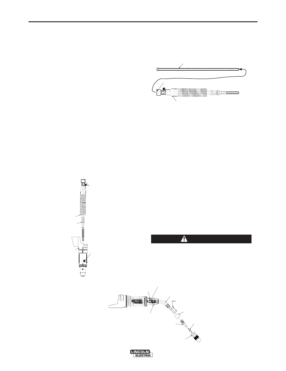
(See Figure D-2 for instructions 6,7)
6. Lay Cable Assembly out straight on a flat surface.
7. Loosen set screw located in the brass feeder con-
nector using 5/64 (2.0 mm) Allen wrench. Pull liner
out of cable.
FIGURE D.2
For installation and trimming instructions for Magnum
liners and wire brake jump/liners see Installation
Section.
GUN TUBES AND NOZZLES
(See Figure D-3)
1. Replace worn contact tips as required.
2. Remove spatter from from contact tip, gas dif-
fuser, insulator and gun tube after each 10 min-
utes of arc time or as required.
3. To remove gun tube from gun, loosen set screw
in nose cone assembly with 3/16" (4.8 mm) Allen
wrench.
4. Pull gun tube out from nose cone assembly. To
reinstall, insert the gun tube, push in as far as
possible, and line up spot face of gun tube
retighten Set Screw.
CABLE CLEANING
Clean cable liner after using approximately 150 (68
kg) pounds of electrode. Remove the cable from the
wire feeder. Remove the contact tip from the gun.
Using an air hose and only partial pressure, gently
blow out the cable liner from the diffuser end.
• Excessive pressure at the start may cause the
dirt to form a plug.
------------------------------------------------------------------------
Flex the cable over its entire length and again blow
out the cable. Repeat this procedure until no further
dirt comes out.
CAUTION
GUN TUBE
3/16” SET SCREW
SPOT FACE
ON GUN TUBE
GAS DIFFUSER
NOSE CONE ASSEMBLY
TIP
GAS NOZZLE
INSULATOR
LINER TRIM
LENGTH
5/8" (16.0 mm)
Figure D.3
REMOVAL, INSTALLATION AND
TRIMMING INSTRUCTIONS FOR
MAGNUM® LINERS
NOTE: The variation in cable lengths prevents the
interchangeability of liners. Once a liner has
been cut for a particular gun, it should not be
installed in another gun, unless it can meet the
liner cut off length requirement. Liners are
shipped with the jacket of the liner extended
the proper amount.
(See Figure D-1 for instructions 1-5)
1. Robot Axis J5 rotated down 90° to help remove
Cable Assembly.
2. Before sliding Cable Assembly out of Robot Arm
unfasten Gas Hose from Fitting and Untighten
Fastener from Autodrive Wire Drive which is hold-
ing brass connector end.
3. Loosen the fasteners holding the hex connection
and feeder connection. Remove Cable Assembly
from robot.
4. Back out Cable Cover.
5. Back out Hex Connection.
FIGURE D.1
4. Back out Cable Cover
2. Before sliding Cable Assembly
out of Robot Arm unfasten
Gas Hose from Fitting and
Untighten Fastener from Autodrive
Wire Drive which is holding
brass connector end.
5. Back out Hex Connection
3. LOOSEN HEX HEAD FASTENER
THEN SLIDE CABLE ASSEMBLY
OUT.
1. Robot Axis J5 rotated down 90°
To help remove Cable Assembly
Replace Cable Liner
7. Loosen set screw located in the brass feeder connector
using 5/64 (2.0 mm) Allen wrench. Pull liner out of cable.
6. Lay Cable Assembly out straight on a flat surface.