Installation – Lincoln Electric IM10149 POWER WAVE ADVANCED MODULE User Manual
Page 11
A-5
INSTALLATION
POWER WAVE
®
ADVANCED MODULE
A-5
outPut CaBLe guIDeLIneS
taBLe a.1
CaBLe SIZeS For ComBIneD LengtHS oF eLeCtroDe anD worK CaBLeS
(ruBBer CoVereD CoPPer - rateD 75°C)**
Percent
Duty
Cycle
60
100
20
40&30
30
40
60
100
60
100
60
2
2
4or5
3
3
2
1
1
1
2/0
1/0
2
2
3
3
3
2
1
1
1
2/0
1/0
2
2
2
2
2
1
1
1
1
2/0
2/0
1
1
1
1
1
1
1
1
1/0
2/0
2/0
1/0
1/0
1/0
1/0
1/0
1/0
1/0
1/0
2/0
3/0
3/0
200
200
225
225
250
250
250
250
300
325
350
amperes
0 to 50 Ft.
50 to 100 Ft. 100 to 150 Ft. 150 to 200 Ft. 200 to 250 Ft.
** Tabledvaluesareforoperationatambienttemperaturesof40°Candbelow.Applicationsabove40°Cmayrequirecableslargerthan
recommended,orcablesratedhigherthan75°C.
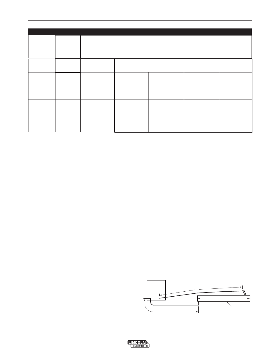
CABLE INDUCTANCE AND ITS EFFECTS
ON WELDING
Excessive cable inductance will cause the welding
performance to degrade. There are several factors
that contribute to the overall inductance of the cabling
system including cable size, and loop area. The loop
area is defined by the separation distance between
the electrode and work cables, and the overall welding
loop length. The welding loop length is defined as the
total of length of the electrode cable (A) + work cable
(B) + work path (C) (see Figure A.4 below). To mini-
mize inductance always use the appropriate size
cables, and whenever possible, run the electrode and
work cables in close proximity to one another to mini-
mize the loop area. Since the most significant factor in
cable inductance is the welding loop length, avoid
excessive lengths and do not coil excess cable. For
long work piece lengths, a sliding ground should be
considered to keep the total welding loop length as
short as possible.
generaL guIDeLIneS
•Selecttheappropriatesizecablesperthe“output
Cable guidelines” (See table a.1. Excessive
voltage drops caused by undersized welding
cablesandpoorconnectionsoftenresultinunsat-
isfactory welding performance. Always use the
largest welding cables (electrode and work) that
arepractical,andbesureallconnectionsareclean
andtight.
note: Excessive heat in the weld circuit indicates
undersizedcablesand/orbadconnections.
•Routeallcablesdirectlytotheworkandwirefeed-
er,avoidexcessivelengthsanddonotcoilexcess
cable. Route the electrode and work cables in
closeproximitytooneanothertominimizetheloop
area and therefore the inductance of the weld cir-
cuit.
•Always weld in a direction away from the work
(ground)connection.
See table a.1 for copper cable sizes recommended
fordifferentcurrentsanddutycycles.Lengthsstipulat-
edarethedistancefromtheweldertoworkandback
to the welder again. Cable sizes are increased for
greaterlengthsprimarilyforthepurposeofminimizing
cabledrop.
B
A
C
POWER
WAVE
FIGURE A.4
WORK