2 rear panel, 3 bottom panel, Figure 1-5: rear view – IEI Integration AFL2-W10A-N28 User Manual
Page 25
AFL2-W10A-N28 Panel PC
Page 7
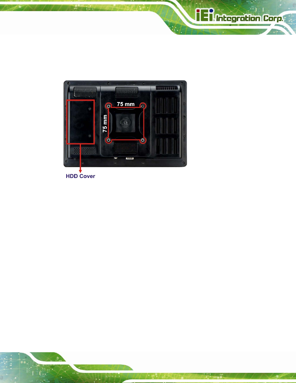
1.2.2 Rear Panel
The rear panel provides access to retention screw holes that support VESA mounting. The
HDD bay is protected by the HDD cover. Refer to
1.2.3 Bottom Panel
The bottom panel of the AFL2-W10A-N28 has the following connectors and switches
1 x 9 V ~ 36 V DC input power jack
1 x Audio line-out jack
1 x AT/ATX switch
1 x Clear CMOS switch
1 x DisplayPort connector
6 x Function keys
1 x GbE RJ-45 connector
1 x Digital microphone
1 x Power button
1 x Reset button
1 x RS-232 DB-9 connector (COM1)
1 x RS-232 RJ-45 connector (COM3)
See also other documents in the category IEI Integration Computers:
- UPC-V312-D525 v1.02 (176 pages)
- UPC-V312-D525 v1.10 (175 pages)
- UPC-12A_GM45 v1.00 (147 pages)
- UPC-12A_GM45 v2.00 (144 pages)
- UPC-12A_GM45 v2.10 (145 pages)
- UPC-V315-NM70 (148 pages)
- UPC-V315-Screw Driver (1 page)
- UPC-V315-QM77 (148 pages)
- S12ASR v1.12 (110 pages)
- S12ASR v3.00 (118 pages)
- PPC-5xxx-9455 v1.00 (198 pages)
- PPC-5xxx-9455 v1.10 (198 pages)
- PPC-WIDS-51xxA-G41 (152 pages)
- PPC-51xxA-H61 (193 pages)
- PPC-5152-D525 v1.02 (183 pages)
- PPC-5152-D525 v2.10 (185 pages)
- PPC-37xxA-N26 v1.00 (203 pages)
- PPC-37xxA-N26 v1.10 (200 pages)
- PPC-37xx-N270 v1.01 (165 pages)
- PPC-37xx-N270 v2.00 (155 pages)
- PPC-37xx-N270 v2.11 (155 pages)
- PPC-37xx-N270 v2.20 (162 pages)
- ACT-457A (67 pages)
- AFL-4 series-N270 v1.05 (165 pages)
- AFL-4 series-N270 v2.10 (166 pages)
- AFL-4 series-N270 v2.11 (168 pages)
- AFL-4 series-N270 v2.20 (168 pages)
- AFL-W19A_W19B_17D_W15A-GM45 v2.10 (138 pages)
- AFL-W19A_W19B_17D_W15A-GM45 v1.06 (138 pages)
- AFL-W19A_W19B_17D_W15A-GM45 v2.20 (151 pages)
- AFL-W15A_17D-GM45 v3.00 (148 pages)
- AFL-15i-HM55 v1.01 (139 pages)
- AFL-19i-HM55 v2.00 (140 pages)
- AFL-15i-HM55 v1.20 (143 pages)
- AFL-W19A_W19B_17D_W15A-N270 v1.06 (125 pages)
- AFL-W19A_W19B_17D_W15A-N270 v2.20 (124 pages)
- AFL-W19A_17D_W15A-N270 v3.00 (126 pages)
- AFL-15A_15AE-N270_UMN_v1.01.pdf (158 pages)
- AFL-15A-N270 v1.03 (159 pages)
- AFL-15A-N270 v2.10 (159 pages)
- AFL-15A-N270 v2.20 (158 pages)
- AFL-xxA-N26 (152 pages)
- AFL-xxA-N270-Series v1.03 (171 pages)
- AFL-xxA-N270-Series v2.00 (171 pages)
- AFL-xxA-N270-Series v2.11 (170 pages)