Sensitivity adjustment – Warner Electric 1300-76 12 Volt Utility Controller for 4, 6, or 8 User Manual
Page 6
6
Warner Electric • 800-825-9050
P-1396 • 819-0301
Sensitivity Adjustment
After the entire controller system is installed and
operating, the controller sensitivity must be
adjusted to synchronize the towing vehicle and
trailer braking systems. Proper adjustment of
your controller/braking system is important
for safe automatic operation.
Warner Electric’s Utility Controller has an
adjustment knob to control trailer brake
sensitivity. This adjustment does not affect
maximum braking capacity of the trailer brakes.
Because of the wide variety of towing vehicles
encountered, balancing towing vehicle brakes
and trailer brakes is necessary for smooth,
synchronized stops. To achieve this, the
controller adjustment should be hand set to
provide a slight lead in trailer braking over tow-
ing vehicle braking. Setting the adjustment in the
“MORE” brake direction will increase the trailer
brake rate of application, while setting in the
“LESS” direction will decrease the trailer brake
rate of application. When proper adjustment has
been achieved, there should be no sensation of
the trailer pushing or pulling the towing vehicle
during a stop. When this setting has been
reached, no further adjustment should be
required. For operating with varying load
weights, read the following section on “Optional
Equipment.”
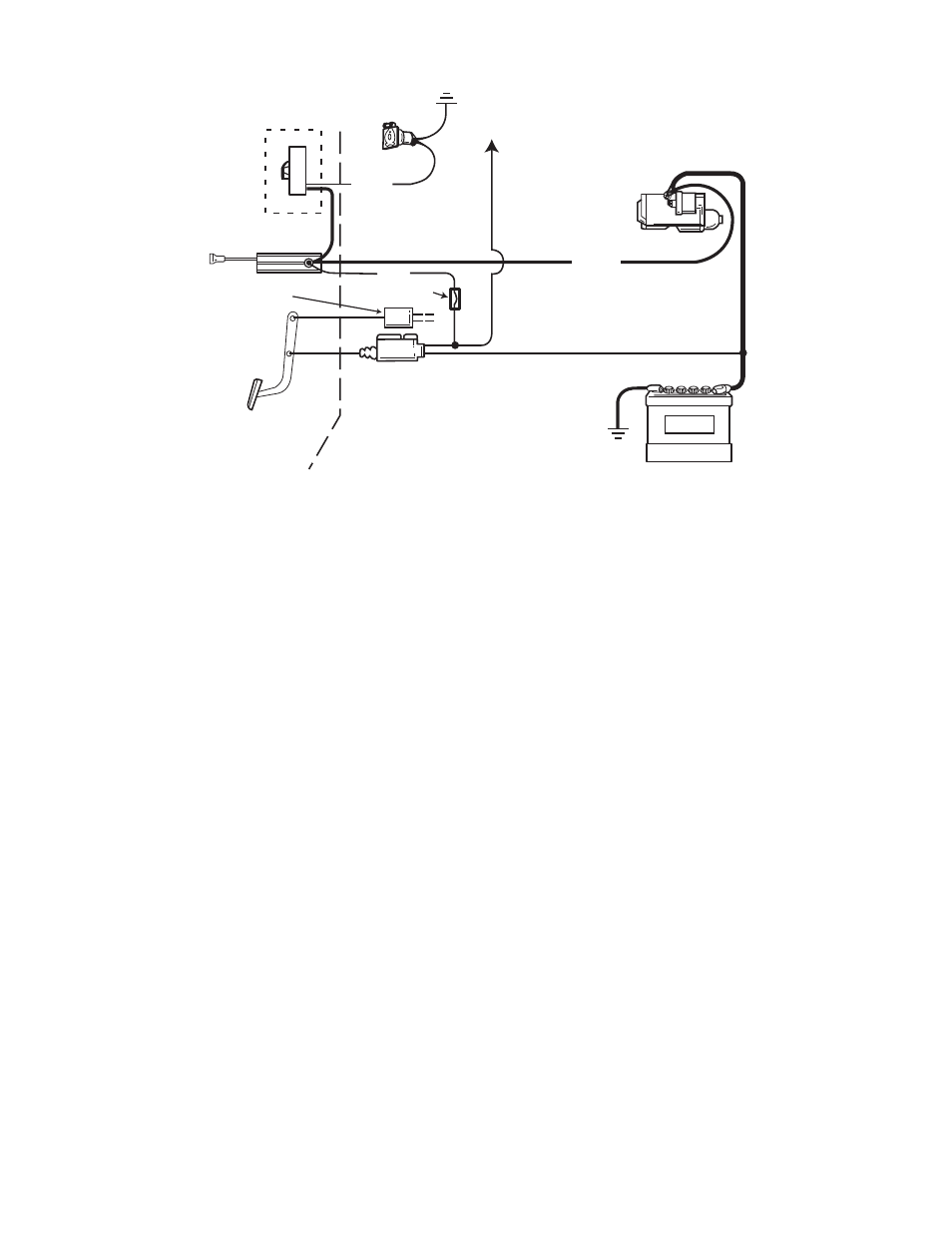
BLUE
SOCKET
TO STOPLIGHT
10 GAUGE WIRE
RECOMMENDED
LOAD CONTROL
1300-78
OPTIONAL
UTILITY CONTROLLER
MOUNTED ON DASH
MECHANICAL
STOPLIGHT
SIGNAL
STOPLIGHT
SWITCH
RED
FUSE
BATTERY
BLACK
10 GAUGE WIRE
RECOMMENDED
STARTER
10. The black or power lead of the controller is
last to be connected. Enough hook-up wire
should remain to make this connection.
Strip one end of this hook-up wire and feed
it through a hole in the firewall from the
engine side. Solder or crimp clamp this
wire to the black controller lead.
11. Detach one of the power cables from the
towing vehicle battery to prevent arcing.
12. Cut the hook-up wire to the proper length
to attach it to the live terminal of the starter
solenoid or relay, strip the wire and
complete the connection. Attaching this
lead completes your electrical connection.
Re-connect the towing vehicle battery
cable.
13. Tape together wires leading from the
controller and secure them to the steering
column or underside of the dash. Plug all
holes in the fire wall with sealant or rubber
grommets to prevent exhaust gases from
entering through the holes and to protect
the wires from abrasion.
Figure 7