Warner Electric 1300-76 12 Volt Utility Controller for 4, 6, or 8 User Manual
Page 4
4
Warner Electric • 800-825-9050
P-1396 • 819-0301
2. On towing vehicles with dual brake systems
(built since 1966) the controller must be
connected to the rear brake portions of
the system.
Note: The rear portion of a master cylinder
does not always control the rear brakes.
Trace the hydraulic tubing to be sure
connections are made in the rear brake
system.
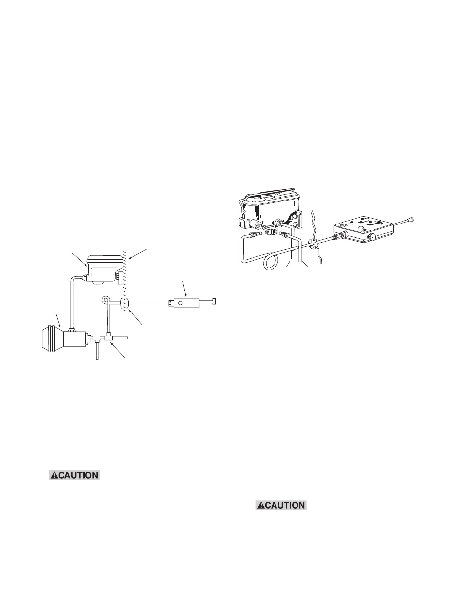
3. Controller Installation in Series Type Power
Brake System. When installing a controller
in a series type power brake system (typically
used in trucks), the connection must be made
on the output side (high pressure side) of the
booster as shown in the figure below.
Determine the correct Tow Craft tee fitting
size by measurement of mating connections.
Figure 4
4. Disconnect the rear supply line at the master
cylinder (except where adapter fitting is used
or when installation is made in a series type
power brake system – see Figure 5) and
install the tee fitting according to the towing
vehicle manufacturer’s recommendations.
Avoid cross-threading and
over-tightening at all connections.
5. Uncoil the tubing provided. Avoid sharp
bending which could cause kinks. Leave one
or more loops of tubing on the engine side of
the firewall to absorb vibration. To insure that
the tubing remains clean, place a rag over the
exposed end. Feed the tubing through a hole
in the firewall, positioning it to avoid hot
engine members or any surface which
could damage it.
6. Connect the tubing to the branch junction
of the tee and tighten the tubing nut (to
approximately 150 in. lbs.).
Figure 5
7. Connect the other end, with male tubing nut,
to the female fitting on the controller cylinder,
but do not hand tighten completely. Take care
not to deform the female thread of the fitting,
which has been pre-tightened during
assembly of the controller.
8. To bleed the hydraulic system, wrap a rag
around this connection and depress the brake
pedal slowly and often enough to fill the
tubing with fluid. All air must be bled from
this line. When hydraulic fluid appears on
the rag, remove it and tighten the tubing nut
securely to stop all leakage (correct torque
approximately 150 in. lbs.), while the pedal is
depressed. The factory installed controller
fitting should not be retightened.
When the tubing nut is
tightened, use a wrench to hold female
fitting. Rocking the female fitting will
cause leakage at the threads.
Master
Cylinder
Fire Wall
Controller
Grommet
and Tape
Tee Fitting
(Connection Made on
Output Side of Booster)
Series
Power
Brake
Typical Installation in Series Type Power Brake System
To Front
Brakes
To Rear Brakes
Grommet
or Sealant
Utility
Controller
Fire Wall
Master Cylinder
Adapter
Tee
Typical hydraulic connection arrangement
showing controller, tubing and tee fitting.