Warner Electric 1300-76 12 Volt Utility Controller for 4, 6, or 8 User Manual
Page 3
Warner Electric • 800-825-9050
P-1396 • 819-0301
3
Installation
These instructions provide for ease of
installation. Please follow them carefully.
The basic installation steps are:
1. Mount the controller inside the towing vehicle.
2. Connect the controller into the towing
vehicle’s hydraulic system.
3. Connect the controller electrically.
4. Adjust the controller for synchronized braking.
Mounting Under Instrument Panel
1. Position the controller under the instrument
panel to the left or right of the steering
column, based on available space and
driver preference.
Mount on Either Side
Figure 1
2. While sitting in a normal driving position,
place the controller so its handle is within
easy reach.
3. Remove the controller cover and, while
holding the controller in place, select at least
two holes through the case which best mount
the controller. Mark the underside of the
instrument panel through these holes.
4. Drill 3/16" diameter holes where marked,
being careful not to damage anything under
the instrument panel.
5. Attach the controller with 3/16" bolts, nuts
and lock washers, and tighten securely. Bolt
heads are to be inside the controller.
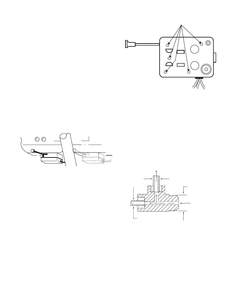
Mounting Holes
Figure 2
Hydraulic Connection
1. To provide for automatic actuation of the
controller, a branch tee must be installed in
the hydraulic brake system. Tees are not
furnished with the controller kit because
requirements vary with different makes and
models of towing vehicles. To determine tee
size, measure A and B dimensions from the
towing vehicle’s master cylinder as illustrated
in Figure 3.
Figure 3
Master Cylinder
Tubing "A" O.D.
Inverted Flare Tube Nut Tee Fittings
For Warner Controllers
Hydraulic Supply
For Rear Brakes
Master Cylinder
Thread Size "B"
3/16 O.D. Tubing Supplied
with Controller
To Controller
F