Warner Electric 1300-76 12 Volt Utility Controller for 4, 6, or 8 User Manual
Page 5
Warner Electric • 800-825-9050
P-1396 • 819-0301
5
4. Remove a knock-out plug or cut a hole in the
firewall near the mounted controller.
5. Cut the wire to a proper length for reaching
the controller. Strip the wire and feed it
through the firewall hole.
6. Connect this wire to the blue brake lead wire
extending from the back of the controller.
Note: Solder or crimp clamp connections
will be required when connecting all three
controller lead wires. Wrap electrician’s
tape around all bare wire joints. Do NOT
use twist-type connectors.
7. Making a chassis ground connection is the
next installation step. Strip one end of the
remaining length of hook-up wire and connect
it securely to the ground terminal of the
socket at the rear of the towing vehicle.
8. Feed the wire under the towing vehicle to a
convenient chassis ground, such as a body
or chassis nut and bolt, battery ground-post,
etc. Cut and strip the wire and attach it
securely to this ground. A good ground
connection is essential for proper
operation.
9. Two Utility Controllers leads are still to be
connected. The red lead actuates the
stoplights when the controller is operated
manually. An interrupted stoplight circuit for
turn signals is used on most towing vehicles.
Connect the controller’s red lead to the output
side of the towing vehicle stoplight switch.
(This switch could be a pressure switch
located in the brake line or a limit switch
activated by the brake pedal.) Connect an
inline fuse in series between the red lead and
the stoplight switch. This fuse should be the
same type and rating as recommended for
the tow vehicle’s existing stoplight circuit.
Splice a short length of hook-up wire to the
red lead to reach the stoplight switch output.
If your towing vehicle has some other system,
consult your automotive dealer.
Figure 6
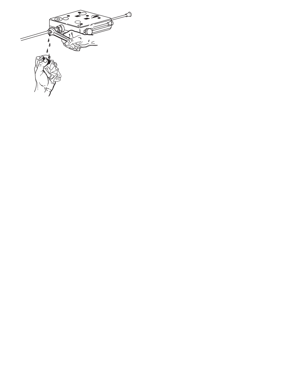
9. To test for sponginess and leaks, pump the
brake pedal and hold it depressed for
approximately one minute. If sponginess
exists, the entire system should be bled at
the wheel cylinders. Refill the master cylinder
fluid reservoir as required.
Electrical Connection
1. Electrical connection is required for all
installations. Approximately 25 ft. of
automotive-type multistranded 12 gauge or
heavier single wire with tough, thermoplastic
insulation meeting SAE standard J558a is
required.
Note: When towing a trailer which will carry
variable loads, or which is light weight when
compared with its brake capacity, a Warner
Electric Load Control part No. 1300-78, may
be required to properly proportion braking
force between the trailer and the towing
vehicle. See Optional Equipment.
2. An electrical socket which mates with the
trailer power cable is to be installed in the
rear of the towing vehicle. Strip one end of
the hook-up wire and connect it to the brake
terminal of this socket.
3. Secure a single length of wire from the brake
connection of the socket to the underside of
the towing vehicle and lead it to the engine
firewall. Position the wire to insure maximum
protection from scraping on the road surface
in rough terrain, flying stones, spray, etc. Also
avoid attaching wires near mufflers and
exhaust pipes. Wires should be clamped at
frequent intervals.