Warner Electric Compressor Clutch Replacement Procedure User Manual
Page 6
6
Warner Electric • 800-825-9050
P-1401 • 819-0316
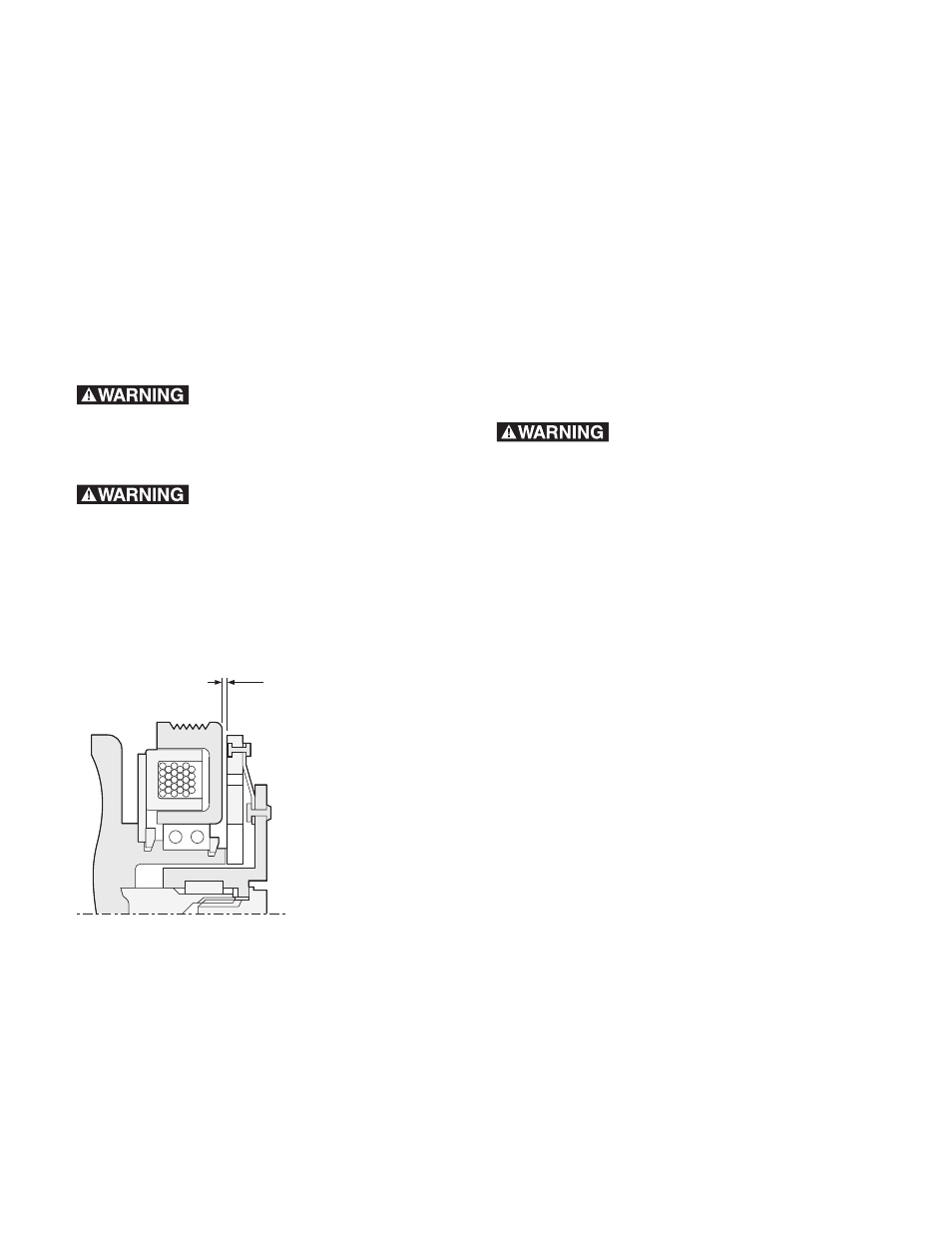
0.020
(0.51)
0.040
(1.02)
Rotor/Pulley to
Hub/Armature Airgap
(Measured 3 places
120° apart)
to
Figure 7
Step 4: Installing the Hub/Armature
Assembly (9)
A. Align the hub keyway with shaft key (7) and
slide the hub/armature (9) onto the compressor
shaft.
B. Set the rotor/pulley to hub/armature air gap at
0.020 to 0.040 inches by adding or removing
shims (8). Measure using a feeler gauge at 3
locations 120° apart. (See Figure 7)
C. Install the lockwasher (10) and shaft nut (11).
Torque to 155 lb.in. using a torque wrench and
spanner wrench.
Use a hub/armature removal
tool (reference Chrysler tool C-4561 or
equivalent) to install and remove the
hub/armature (9).
Do not use screwdrivers
between the hub/armature and rotor/pulley
to remove hub/armature as clutch will be
damaged.
Note: The shims (8) may compress when the
shaft nut (11) is tightened; therefore, recheck
the airgap at three locations 120° apart.
Step 5: Clutch Assembly Check
A. Rotate the clutch and check for rubbing or
interference.
B. Reinstall belts per manufacturer's service
manual. Do not over tighten.
C. Recheck the airgap at 3 or 4 points and
check for clutch rubbing.
D. Important: Burnish as follows. Run the
clutch at 2500 to 3000 RPM. Cycle the clutch
ON and OFF at a rate of 10 to 15 times per
minute maximum for a total of 50 cycles
minimum. This should bring the clutch up
to operating torque capacity.
Cycle the clutch using the
controls inside the car or electrical system
damage could result.