Step 1: diagnose clutch failure, Step 2: removal of hub/armature assembly (9), Ford – Warner Electric Compressor Clutch Replacement Procedure User Manual
Page 2: Chrysler, Tecumseh, Fs-6, C-171, Hr980
2
Warner Electric • 800-825-9050
P-1401 • 819-0316
Failure to follow these
instructions may result in product damage,
equipment damage, and serious or fatal
injury to personnel.
Note: During compressor clutch removal DO
NOT pound on the clutch or compressor as
damage will result.
Step 1: Diagnose Clutch Failure
Most compressor clutch failures are a direct
result of an A/C system problem or failure.
Before installing a new clutch, determine what
caused the old clutch to fail and fix the system
problem. By simply re placing the clutch without
fixing the cause of the clutch failure, the new
clutch may fail in the same manner as the old
clutch. Please refer to the Warner Electric "Air
Conditioning Clutch Trouble Shooting Guide"
and the appropriate manufacturer's A/C
Service Manuals.
Step 2: Removal of Hub/Armature Assembly
(9)
Special tools must be used to avoid damaging
the compressor.
A. Remove shaft nut (11) with a 13mm socket
wrench and spanner wrench.
B. Remove lock washer (10).
C. Remove hub/armature (9) with a hub/armature
removal tool (reference Chrysler Tool # C-4561
or equivalent).
D. Remove shims (8) from the hub/armature and
shaft.
Step 3A: Removal of Rotor/Pulley Assembly
(4) (All compressors except HR980)
A. Remove rotor/pulley snap ring (5).
B. Slide rotor/pulley assembly (4) off the
compressor (1) nose. If rotor/pulley assembly
is hot and will not slide, DO NOT FORCE! Allow
the clutch to cool and then proceed.
C. Proceed to Step 4.
Warner Replacement Clutches
for the following compressors:
Denso
6E171
10P15
6P148
6C17
Ford
FS-6
Chrysler
C-171
Tecumseh
HR980
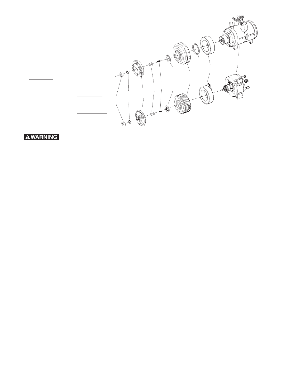
11
Shaft Nut
10
Lock
Washer
8
Shims
7
Key
6
Rotor/Pulley
Retainer nut
4
Rotor/Pulley
Assembly
2
Field Coil
1
Compressor
9
Hub/Armature
Assembly
5
Rotor/Pulley
Snap Ring
3
Field Coil
Snap Ring
HR980
FS6, C171, A590,
6E171, 10P15,
6P148, 6717