Vanguard ATO-600P User Manual
Page 16
ATO-400P / ATO-600P Operating Procedures
16
6.0 CABLE CONNECTION
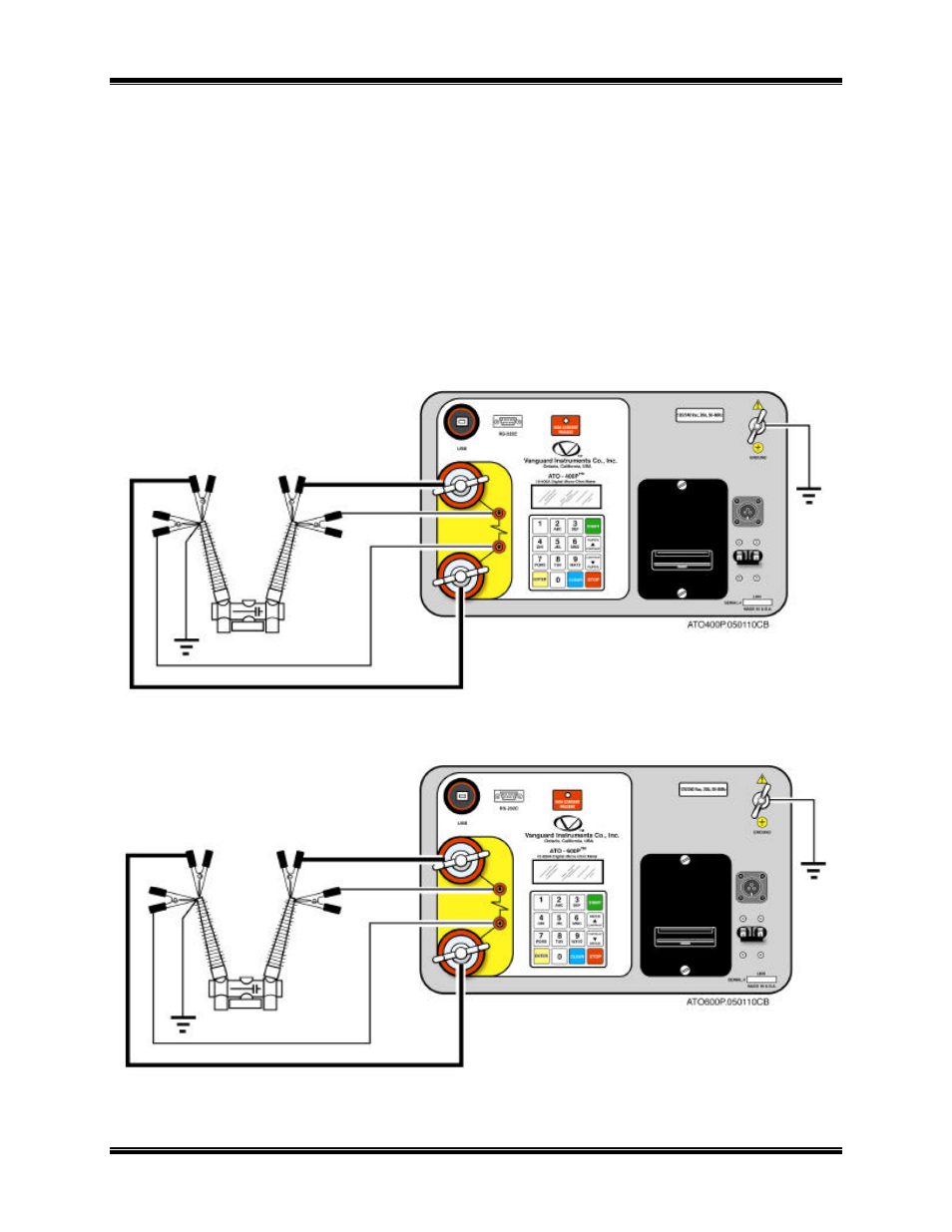
The ATO is supplied with 15-foot (#1/0 AWG) current-carrying cables and 15-foot voltage-
sensing cables. Both cables are terminated with heavy-duty alligator clamps to connect to the
device being tested. A typical cable connection for the ATO to a device under test is shown in
figure 6 and figure 7. To protect the ATO against static discharge in the substation, always
connect the unit’s ground stud to the substation ground. It is also highly recommended to ground
one side of the circuit breaker bushing during testing to eliminate any static discharge through
the ATO.
NOTE
The sense input is not polarity sensitive. The sense cables may be
connected to either input without affecting circuit operation.
Figure 6 ATO-400P Connection Diagram
Figure 7 ATO-600P Connection Diagram