2 master-slave operation 7-4, Connecting the instruments 7-4, Master-slave operation, 7-4 – Anritsu 681XXC User Manual
Page 208: Master-slave operation -4, Connecting the instruments -4, Use with master-slave other instruments operation
7-2
MASTER-SLAVE
OPERATION
Master-slave operation consists of connecting any two 68XXXC and/or
68XXXB instruments together and configuring them so that they pro-
duce CW and synchronized, swept output signals at an operator-
selectable frequency offset. One instrument (the Master) controls the
other (the Slave) via interface cables between their rear panel
AUX I/O
and
SERIAL I/O
connectors. The two units are phase-locked together
by connecting them to the same 10 MHz reference time base.
Connecting
the Instru-
ments
Connect the two instruments, shown in Figure 7-1,
as follows:
Step 1
Connect the 3-port AUX I/O cable end la-
beled “MASTER” to the rear panel
AUX
I/O
connector on the Master instrument.
Connect the AUX I/O cable labeled
“SLAVE” to the rear panel
AUX I/O
con-
nector on the Slave instrument.
Step 2
Connect the ends of the flat interface ca-
ble to the rear panel
Serial I/O
connectors
on the Master and Slave instruments.
Step 3
Connect one end of a coaxial cable to the
rear panel
10 MHz REF OUT
connector on
the Master instrument. Connect the other
end to the rear panel
10 MHz REF IN
con-
nector on the Slave instrument.
7-4
681XXC OM
USE WITH
MASTER-SLAVE
OTHER INSTRUMENTS
OPERATION
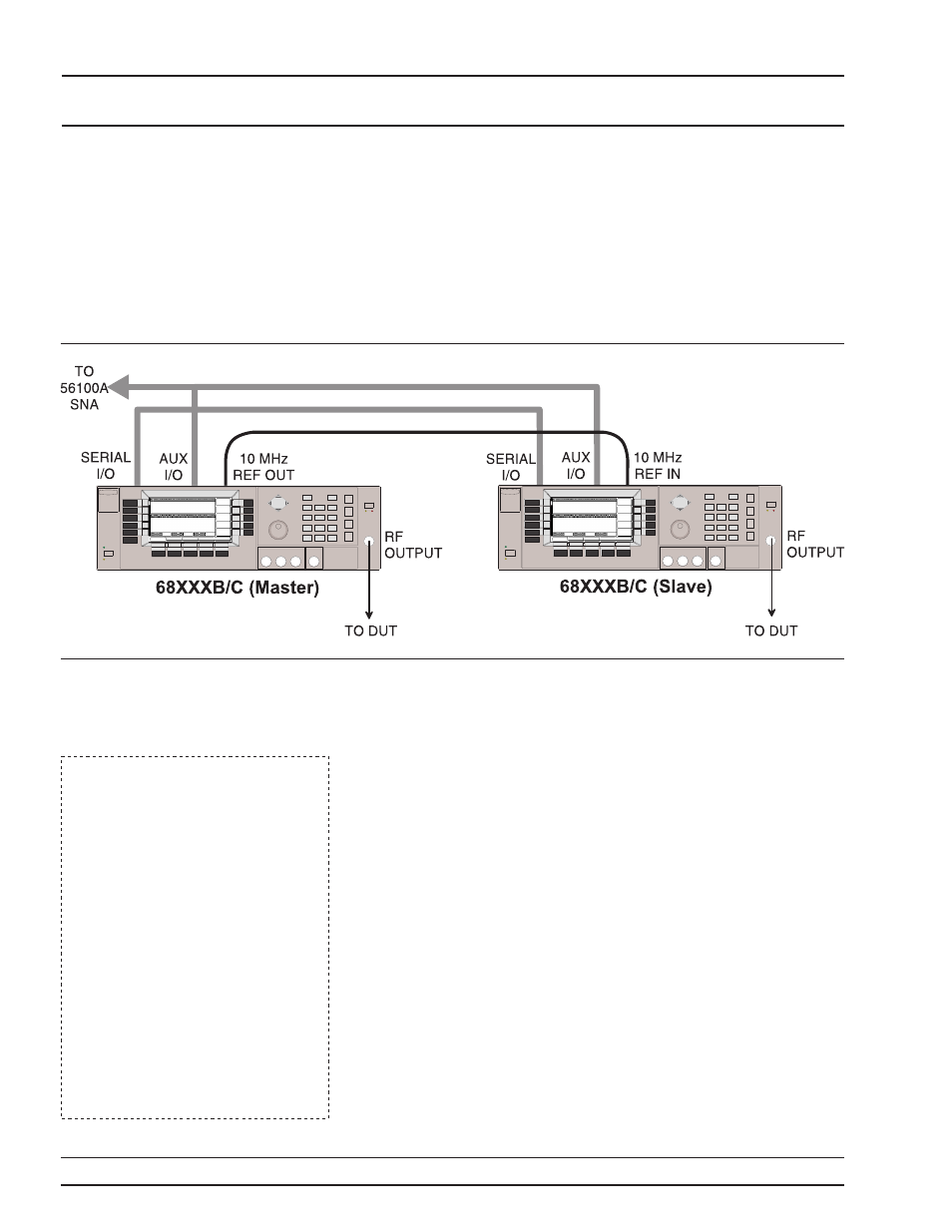
Figure 7-1.
68XXXB/68XXXC Configuration for Master-Slave Operation
NOTES
When connecting two instruments
together for Master-Slave opera-
tions, always use a Anritsu
Master-Slave interface cable set,
Part No. ND36329.
If a Model 56100A Scalar Network
Analyzer is being used with the
master-slave configuration, (1) con-
nect the AUX I/O cable end labeled
“SNA” to the rear panel
AUX I/O
connector on the 56100A SNA and
(2) connect a dedicated system bus
cable (P/N 2100-1) between the
Master instrument rear panel
IEEE-488 GPIB
connector and the
56100A SNA rear panel
DEDI-
CATED GPIB
connector.