6 power level accuracy and flatness tests 5-13, Test setup 5-13, Test setup, 5-13 – Anritsu 681XXC User Manual
Page 157: Power level accuracy and flatness, 5-13, Power level accuracy and flatness, Tests -13, Test setup -13
5-6
POWER LEVEL
ACCURACY AND
FLATNESS TESTS
These tests verify that the power level accuracy and flatness of the
681XXC meet specifications. Table 5-3, beginning on page 5-19, con-
tains test records that you can copy and use to record test results for
these tests. Test records are provided for each 681XXC model configu-
ration.
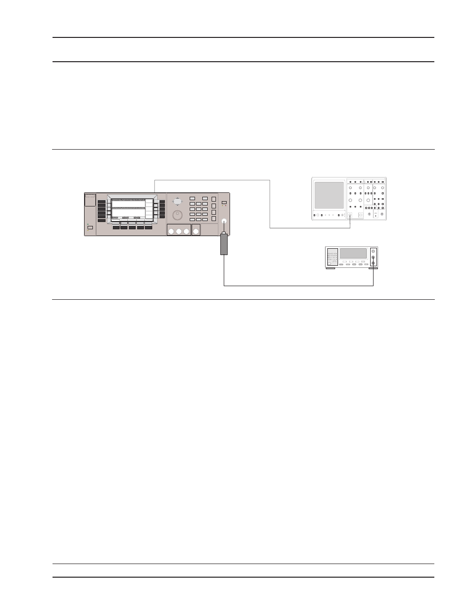
Test Setup
Connect the equipment, shown in Figure 5-2, as
follows:
Step 1
Calibrate the Power Meter with the
Power Sensor.
NOTE
For
£40 GHz models, use the
M A 2 4 7 4 A p o w e r s e n s o r ; f o r
>40 GHz models, use the MA2475A
power sensor.
Step 2
Connect the Power Sensor to the
RF OUT-
PUT
of the 681XXC.
Step 3
Connect the 681XXC rear panel
HORIZ
OUT
to the Oscilloscope CH.1 input (X in-
put).
NOTE
Before starting these procedures,
locate the test record in Table 5-3
for the particular 681XXC model
configuration being tested.
681XXC OM
5-13
OPERATION
POWER LEVEL ACCURACY
VERIFICATION
AND FLATNESS TESTS
R F
O U T
H O R I Z
O U T
6 8 1 X X C S I G N A L G E N E R A T O R
O S C I L L O S C O P E
P o w e r
S e n s o r
P O W E R M E T E R
C H 1 o r X I n p u t
Figure 5-2.
Equipment Setup for Power Level Accuracy and Flatness Tests