Teledyne LeCroy HDO 4000 Operators Manual User Manual
Page 75
HDO4000 High Definition Oscilloscope
FFT
For a large class of signals, you can gain greater insight by looking at spectral representation rather than
time description. Signals encountered in the frequency response of amplifiers, oscillator phase noise and
those in mechanical vibration analysis, for example, are easier to observe in the frequency domain.
If sampling is done at a rate fast enough to faithfully approximate the original waveform (usually five
times the highest frequency component in the signal), the resulting discrete data series will uniquely
describe the analog signal. This is of particular value when dealing with transient signals because, unlike
FFT, conventional swept spectrum analyzers cannot handle them.
Because of its versatility, FFT analysis has become a popular analysis tool. However, some care must be
taken with it. In most instances, incorrect positioning of the signal within the display grid will significantly
alter the spectrum, producing effects such as leakage and aliasing that distort the spectrum.
An effective way to reduce these effects is to maximize the acquisition record length. Record length
directly conditions the effective sampling rate of the oscilloscope and therefore determines the frequency
resolution and span at which spectral analysis can be carried out.
Set Up FFT
1. Follow the usual steps to
, selecting FFT from the Frequency Analysis submenu.
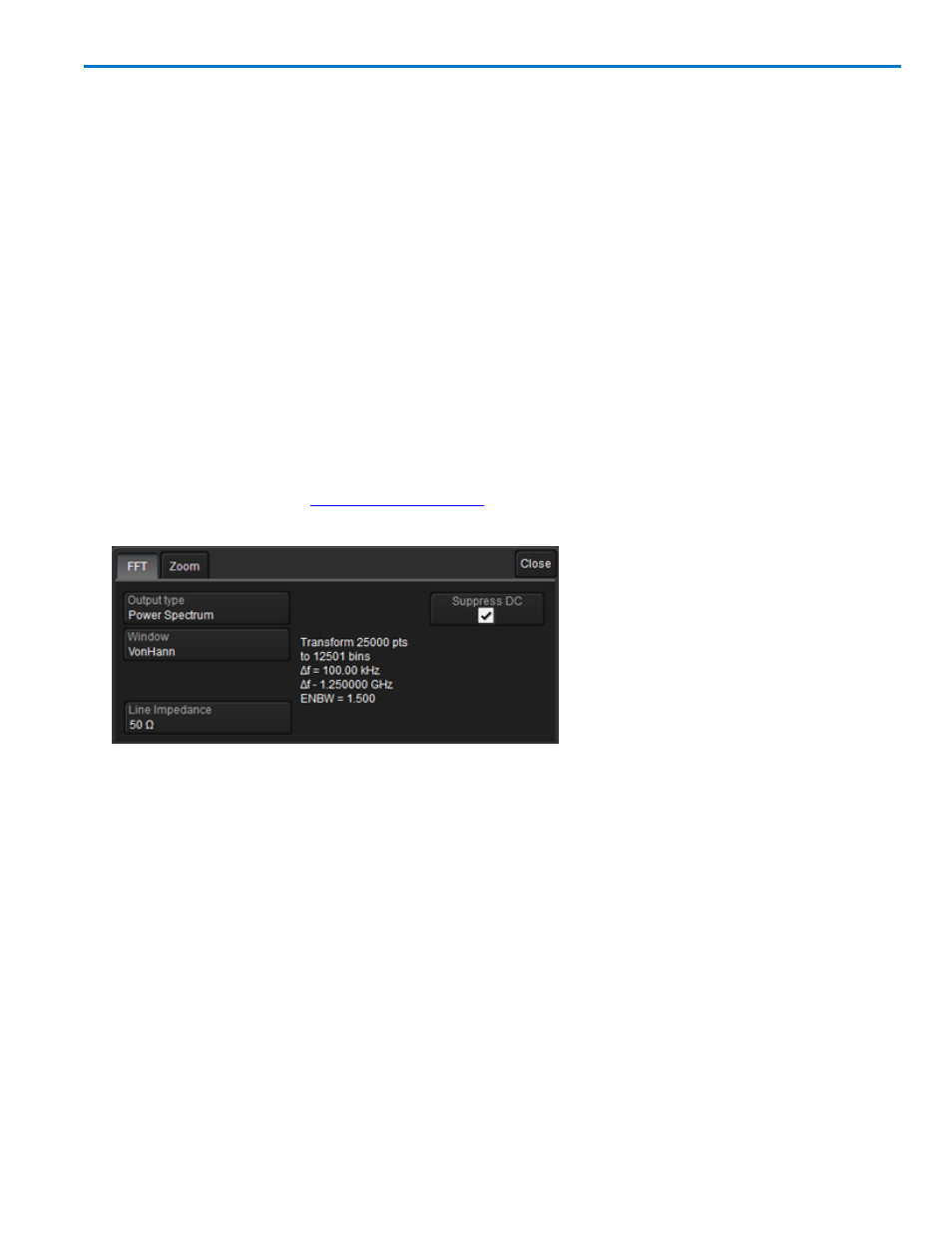
2. Open the FFT right-hand dialog.
3. Check the Suppress DC box to make the DC bin go to zero. Otherwise, leave it unchecked.
4. Choose an Output type.
5. Optionally, choose a weighting Window. See the section below for more information about FFT
weighting windows.
6. Depending on your Output Type selection, you may also make selections for Line Impedence. By
default, the FFT function assumes that the oscilloscope is terminated in 50 Ohms. If an external ter-
minator is being used, this setting can be changed to properly calculate the FFT based on the new ter-
mination value.
Choosing a Window
The choice of a spectral window is dictated by the signal's characteristics. Weighting functions control
the filter response shape, and affect noise bandwidth as well as side lobe levels. Ideally, the main lobe
should be as narrow and flat as possible to effectively discriminate all spectral components, while all
side lobes should be infinitely attenuated. The window type defines the bandwidth and shape of the
equivalent filter to be used in the FFT processing.
922498 Rev B
67