Signal display grid – Teledyne LeCroy HDO 4000 Operators Manual User Manual
Page 19
HDO4000 High Definition Oscilloscope
Signal Display Grid
The grid area displays the waveform traces. It is sectioned into 10 Horizontal (Time) divisions and 8
Vertical (Voltage) divisions.
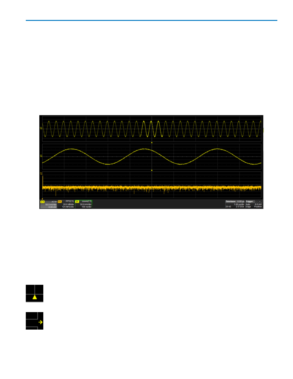
Multiple Grid Display
By default, the oscilloscope has Auto Grid enabled. This divides the screen into a maximum of three grids,
one each for channels/memories, math functions, and zooms. All traces of the same type appear on the
same grid.
To display all types of traces on a single grid, choose Display > Single Grid from the menu bar.
Two special grid layouts are available: XY Grid, which puts the oscilloscope in XY mode, and XY Single
Grid, which creates one XY grid and one single grid for the rest of your traces.
Different types of traces opening in separate grids.
Adjusting Grid Brightness
You can adjust the brightness of the grid lines to make either the grid or traces more visible. Go to
Display > Display Setup and enter a new Grid Intensity percentage. The higher the number, the brighter
and bolder the grid lines.
Grid Indicators
These indicators appear over the grid to mark important points on the display. They are matched to the
color of the trace to which they apply.
Trigger Position - A small triangle along the bottom (horizontal) edge of the grid shows the time
the oscilloscope is set to trigger an acquisition. Unless Delay is set, this indicator is at the zero
(center) point of the grid. Trigger Delay is shown at the top right of the Timebase descriptor box.
Pre/Post-trigger Delay - A small arrow to the bottom left or right of the grid indicates that a pre-
or post-trigger Delay has shifted the Trigger Position indicator to a point in time not displayed
on the grid. All trigger Delay values are shown on the Timebase Descriptor Box.
922498 Rev B
11