Setting mode of operation, Dip switch, Cross zone – System Sensor PDRP-1002 User Manual
Page 26
3 Installation Procedure
DIP Switch
26
The PDRP-1002 PN 51135:A 03/11/99
Setting Mode of Operation
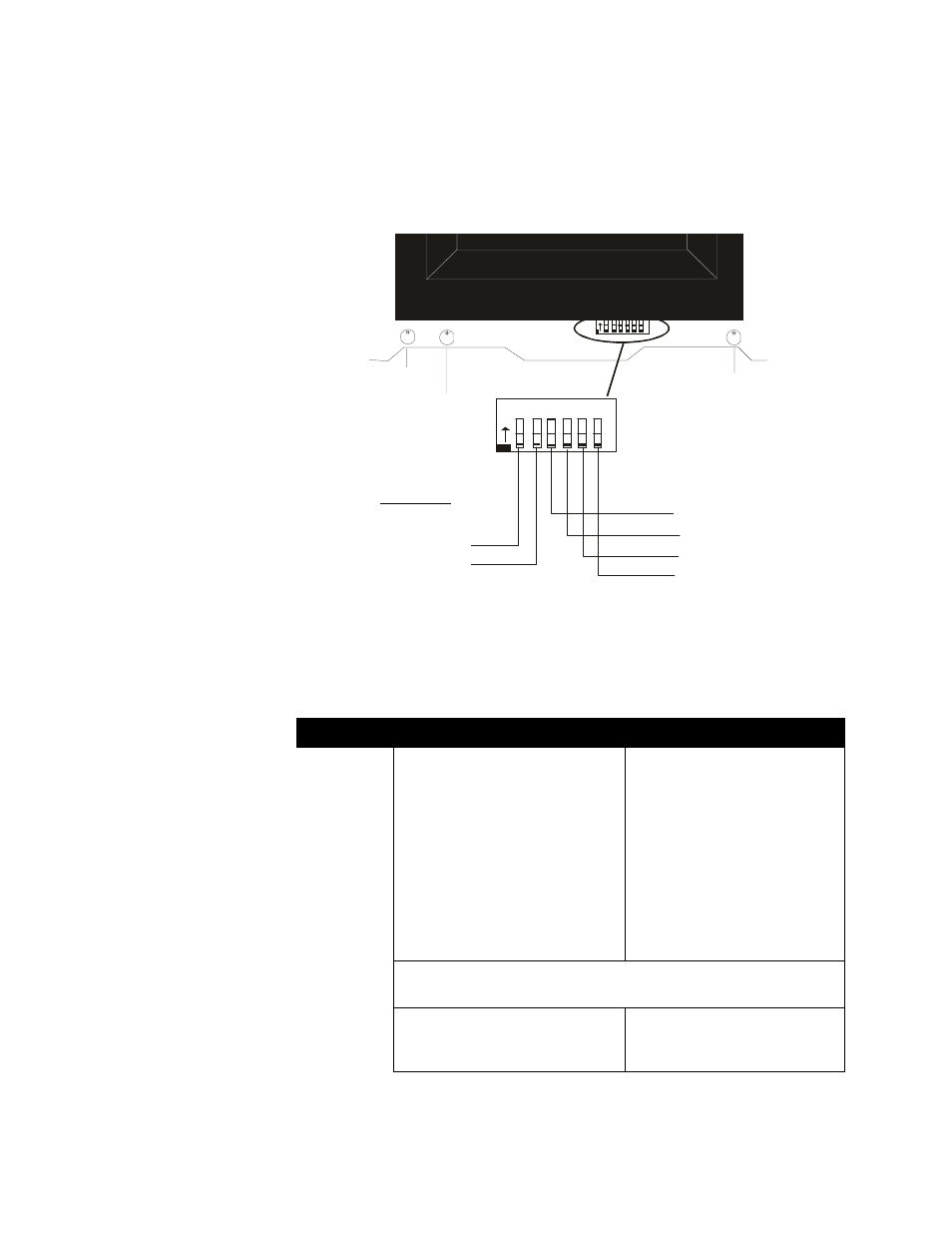
DIP Switch
The DIP switch is located at the bottom of the PDRP-1002/PDRP-1002E main board.
To set a switch to the “ON” position, slide the switch up until it stops. The flush-
surface switches are designed to prevent accidentally changing a switch setting and may
therefore require use of a pen or screwdriver to set them.
Note: The Reset key must be depressed after any switch configuration has been made.
Cross Zone
Select the desired mode of operation and set SW1 DIP switch 1.
Note: Outputs 1 and 2 refer to Notification Appliance Circuits. Output 3 refers to a releasing circuit. Output
4 is determined by setting switch 2. Zones 1 and 2 refer to Initiating Device Circuits.
Switch 1
OFF
ON
Output 1 is activated by an alarm on
either Zone 1 or Zone 2.
Output 1 (Pre-discharge alarm) is
activated by the first alarmed zone
in the system. Initiation of an alarm
on the other zone will shut this
output off.
Output 2 is activated by an alarm on
either Zone 1 or Zone 2. Output 2
will pulse at 60 ppm while timer is
running or frozen by abort. Output 2
will sound steadily upon release (time
out).
Output 2 is activated when alarms
occur on both Zone 1 and Zone 2.
Output 2 will pulse at 60 ppm while
timer is running or frozen by abort.
Output 2 will sound steadily upon
release (time out).
Outputs 3 and 4 will be activated when the timer expires (provided that
Output 4 is functioning as a releasing circuit - set via DIP Switch 2).
The Timer will start whenever an
alarm occurs on either Zone 1 or
Zone 2.
The Timer will start when alarms
occur on both Zone 1 and Zone 2.
1 2 3 4 5 6
O
N
1 2 3 4 5 6
O
N
Battery Fail
LED
Ground Fault LED
Micro Fail LED
Switch 3: DELAY TIMER
Switch 4: DELAY TIMER
Switch 5: ABORT OPTION
Switch 6: ABORT OPTION
Switch 1: CROSS ZONE
Switch 2: SUPERVISORY
4
X
RP
DI
P
S
.c
d
r
DIP Switches