Push to reset out, Push to reset, Surge battery – Staub Electronics EP-400-UPS-8HTR-1000 EPISODE - SURGE RACK MOUNT, 20AMP 8-OUTLET 2U UPS AVR User Manual
Page 2
Push To
RESET
OUT
Serial Port I
(PRIMARY)
Serial Port II
IN
SURGE
BATTERY
+
Push To
RESET
+
SURGE
BATTERY
AC INPUT
EPO
FAULT
WIRING
IN
OUT
POWER SUPPLY
E187679
6G48
R
UNINTERRUPTIBLE
LISTED
C
US
Push To
RESET
LOAD
CRITICAL
NONCRITICAL
LOAD
ON/OFF
SELECT
HARDWARE INSTALLATION GUIDE CONT.
7. Your UPS is equipped with an auto-charge feature. When the UPS is plugged into an AC outlet, the battery will be automatically charging, even when the unit is switched off.
8. In order to maintain an optimal battery charge at all times, leave the UPS plugged into an AC outlet at all times.
9. Before storing the UPS for an extended period of time, turn the unit OFF. Then cover it and store it with the batteries fully charged. Recharge the batteries every three months
to ensure good battery capacity and long battery life. This may also prevent damage to the unit from unlikely battery leakage.
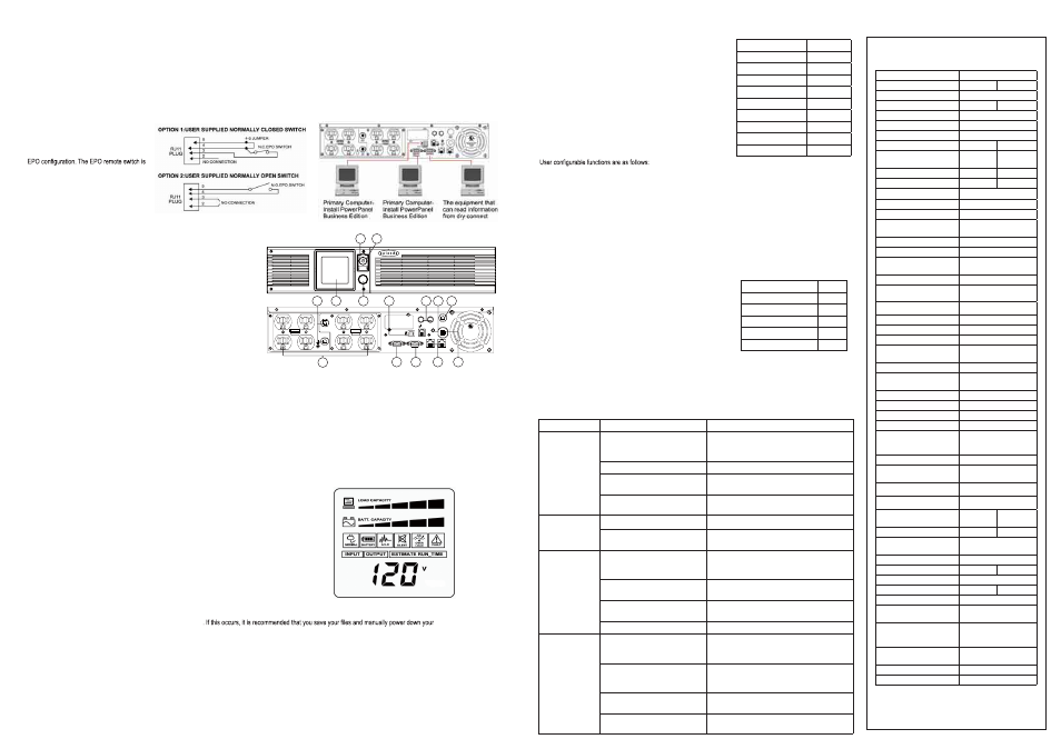
10. The unit provides one Primary Serial Port (I), Secondary Serial Port (II), and one USB port, (paired with the Primary Serial Port), to allow connection and communication between
the unit and any attached computers. The Primary Serial Port (I) as well as its paired USB port allow for bi-directional communication among the UPS and the primary connected
computer running the PowerPanel® Business Edition S/W provided. The UPS can control the computer’s shutdown in case of an emergency, and at the same time, the computer
can monitor the UPS and alter its various programmable parameters. On the other hand, secondary Serial Port II only allows the UPS to initiate the connected computer’s smart
auto-shutdown in case of an emergency.
11. EPO (Emergency Power Off) Port: Use the
provided cable to connect to the special
EPO contact switch. Follow the appropriate
circuit diagram (right) to wire the cable to your
a switch installed in an outside area, connected
to the unit via an ordinary RJ-11 phone line.
In case of an emergency, it can be used to
immediately cut-off power from the UPS.
DEFINITIONS FOR ILLUMINATED LCD INDICATORS:
INPUT voltage meter: Measures the AC voltage that the UPS system is receiving from the utility wall
outlet. The INPUT voltage readout can be used as a diagnostic tool to identify poor-quality input power.
The AVR in this UPS continuously conditions the power to a stable 110/120V output to connected
equipment. In the event of a complete power loss, severe brownout, or over voltage, the UPS relies
on its internal battery back up to supply a consistent 110/120V output.
OUTPUT voltage meter: Measures, in real time, the AC voltage that the UPS system is
providing to the computer, such as normal line mode, AVR mode and battery back up mode.
Note: The OUTPUT voltage readout displays the status of the battery back-up outlets.
ESTIMATE RUN TIME: Displays the run time estimate of the UPS with the current battery capacity and load.
NORMAL icon: Appears when the UPS is working under normal conditions.
BATTERY icon: During a severe brownout or blackout, this icon appears and an alarm sounds (two short beeps
followed by a pause) to indicate the UPS is operating from its Internal batteries. During an extended brownout or
blackout that drains the battery, a continuous alarm will sound (and the BATT. CAPACITY readout will show a single shaded segment, equaling 20% battery
capacity remaining) indicating the UPS batteries are nearly out of power
equipment immediately.
AVR (Automatic Voltage Regulation) icon: Appears whenever your UPS is automatically correcting low AC input line voltage without using battery power. This
is a normal, automatic operation of your UPS, and no action is required.
SILENT MODE icon: Appears whenever the UPS is in silent mode. The buzzer does not beep during silent mode until the battery reaches low capacity.
OVER LOAD icon: Appears and an alarm sounds to indicate the battery-supplied outlets are overloaded. To clear the overload, unplug some of your equipment
from the battery-supplied outlets until the icon turns off and the alarm stops.
FAULT icon: Icon appears if there is a problem with your UPS.
BATT. CAPACITY meter: Displays the approximate charge level (in 20% increments) of the UPS’s internal battery. During a blackout or severe brownout and the
UPS switches to battery back up power, the BATT. CAPACITY icon appears and the charge level decreases.
LOAD CAPACITY: Displays the approximate output load level (in 20% increments) of the UPS’s battery outlets.
BASIC OPERATION
PRODUCT FEATURES
1. Power Switch: Master on/off switch for equipment connected to the UPS.
2. Power On Indicator: Indicates the power is on.
3. LCD Module Display: LCD shows all the UPS information with icons and messages.
4. LCD Display Toggle Button: The button can be used to toggle between different data
displays on the LCD.
5. Battery Backup Protected Outlets: Provides eight battery powered, surge protected
and AVR outlets for connected equipment and ensures temporary uninterrupted
operation of connected equipment during a power failure.
Critical /Non-critical: When the UPS is overloaded, the circuit breakers will be tripped
to interrupt the power supply to the uncritical outlets while continuing to supply the
critical outlets. As well, as the battery capacity depletes under the threshold value,
the uncritical outlets will be shut down and provide energy for critical outlets. The
threshold can be determined and set by users. Non-critical outlets can also be turned
on/off manually through the software package provided.
6. Input Power Cord: Heavy-duty, extra long power cord.
7. Output Circuit Breaker: Resettable circuit breakers provide Output outlets protection
from
overload.
8. Input Circuit Breaker: Resettable circuit breakers provide Input outlets optimal
overload
protection.
9. USB port: USB communication port for management software.
10. Protected Communication Ports RJ11/RJ45: Ports protect standard single line
modem, fax, telephone line or network cable.
11. Site Wire Fault Indicator: This LED will illuminate to warn the user that a wiring
problem exists within the AC receptacle, such as a bad ground or reversed
wiring. If illuminated, disconnect all equipment and contact an electrician to
ensure outlet is properly wired.
12. Coax/Cable/DSS Surge Protection: The Coax/Cable/DSS surge protection ports
will protect any cable Modem, CATV converter or DSS receiver.
13. Serial Port I: Serial port allows connection and communication between the UPS
and the computer.
14. Serial Port II: Serial Port II relays information to equipment that can utilize a
contact closure UPS.
LCD STATUS AND SETUP FUNCTIONS
1. General Mode:
a. Press the “Display” button to check the status of the UPS.
b. Press and hold the Display toggle for 4 seconds:
- If machine is in Battery Mode, it will enter Mute status.
- If machine is in Line Mode, it proceeds Self Test.
c. If the Display toggle remains untouched for over 30 seconds,
the LCD backlight will turn off automatically.
2. Set-up Mode
Step 1: The machine enters Set-Up Mode after holding the Display
toggle for 10 seconds. Icons 3,4,5,6,7,8 light to indicate Set-Up Mode.
Step 2: By pressing the Display toggle, users can switch between
setup
functions.
a. Delay Time: Delay between switching from Battery Mode to Line Mode. There are 9 different
settings. The default setting is 0 minutes.
b. Battery Pack Numbers: Provides the estimated UPS runtime using various numbers of battery packs.
The default setting is 0.
c. Static Frequency Tolerance: There are 6 settings. The default setting is +/-6%.Functional description: The
setting may be adjusted to the quality of the electricity in use.
d. Slew rate (Dynamic Frequency Tolerance): There are 5 different settings, and the fault value is 4Hz/ sec.
Functional Description: “Slew Rate” indicates the tolerance of a device in accepting frequency variance.
The lower “Slew Rate” results in less tolerance, but better protection for the connected loads.
e. Battery Shutdown Voltage: This function adjusts the UPS shutdown point according to the battery voltage.
The settable items are sorted by unit as in the following table:
Step 3: Press and hold the toggle for 4 seconds. When the icons blink,
the value of each item can be changed by slightly pressing the toggle.
Step 4: To save the value and return to general mode, press and hold
the toggle for 4 seconds.
Note: If the machine is left idle for over 30 seconds during setup,
the backlight will turn-off and return to general mode automatically.
Note: If user wants to return to general mode without saving changes, there are two methods:
1. Wait for the backlight to turn off OR 2. Press and hold the “Display” toggle for 10 seconds.
Item
Unit
Input Voltage
V
Output Voltage
V
Output Frequency
Hz
Load
Kw
Estimate Run Time
Min
Load Capacity
%
Battery Capacity
%
Centigrade
°C
Fahrenheit
°F
Item
Unit
Delay Time
Min
Battery Pack Numbers
A
Static Frequency Tolerance
%
Slew Rate
Hz
Battery Shutdown Voltage
V
2
1
3
7
9
12 11 8
6
10
14
13
5
4
TROUBLE SHOOTING
PROBLEM
POSSIBLE CAUSE
SOLUTION
Outlets do not
provide power
to equipment.
Circuit breaker has tripped due to an
overload.
Turn the UPS off and unplug at least one piece of
equipment. Wait 10 seconds, reset the circuit breaker
by depressing the button, and then turn the UPS on.
Batteries are discharged.
Recharge the unit for at least 4 hours.
Unit has been damaged by a surge
or spike.
Contact SnapAV™ about replacement batteries at
866.838.5052.
Uncritical outlets have turned off
automatically due to an overload.
Push the toggle button to make the uncritical outlets
turn on.
The UPS does not
perform expected
runtime.
Battery not fully charged.
Recharge the battery by leaving the UPS plugged in.
Battery is worn out.
Contact SnapAV™ about replacement batteries at
866.838.5052.
The UPS will not
turn on.
The on/off switch is designed to
prevent damage by rapidly turning it
off and on.
Turn the UPS off. Wait 10 seconds and then turn the
UPS on.
The unit is not connected to an AC
outlet.
The unit must be connected to a 110/120v 60Hz
outlet.
The battery is worn out.
Contact SnapAV™ about replacement batteries at
866.838.5052.
Mechanical problem.
Contact SnapAV™ at 866.838.5052
PowerPanel®
Personal Edition is
inactive
(all icons are gray).
The USB cable is not connected.
Connect the USB cable to the UPS unit and an open
USB port on the back of the computer.
The provided USB cable must be used.
The unit is not providing battery
power.
Shutdown your computer and turn the UPS off. Wait
10 seconds and turn the UPS back on. This should
reset the unit.
The cable is connected to the wrong
port.
Try another port of the computer.
The serial cable is not the cable that
was provided with the unit.
Replace with provided USB cable.
Product Dimensions
17.25 x 15.75 x 3.5 (LXWXH)
Weight
52 lb.
63 lb.
Rack Size
2U
AC Input Plug Type
Nema 5-15P Nema 5-20P
Cable Length
10 ft
Operating Temperature
32ºF to 95ºF (0ºC to 40ºC)
Automatic Voltage Regulation
Yes
Amperage
15
20
AC Outlets & Plug Type
8 x Nema
5-15R
8 x Nema
5-20R
Output VAC
1000
2170
Output Watts
700
1600
UPS Topology
Line-Interactive
Operating Humidity
0%~95% non condensing
Storage Temperature
5ºF to 113ºF (-15ºC to 45ºC)
Number. of RJ11/ RJ45 Con-
nectors
1 pair (1-in, 1-out)
RJ11/ RJ45 Clamping Level
310 V for RJ11, 6.8 V for RJ45
Coaxial No. of Pairs
1
COAXIAL Gold Plated “F” Con-
nectors
Yes
Coax/Cable/DSS Surge Protection Yes
Coaxial Insertion Loss
< 1 dB (rated for DSS) (up to
2.0 GHz)
Coaxial Breakdown Voltage
300V
Coaxial Bidirectional?
Yes
Input Voltage Range (VAC)
80~150
Output Plug Style
Right Angle
Resettable Circuit Breaker
Yes (2 resettable circuit
breakers)
Number of Total Outlets
8
Number of Surge & Battery
Backup Outlets
8
Battery Voltage (VAC)
120 +/- 7% (pure sine wave)
Line Frequency (Hz)
60 +/- 3
Battery Frequency (Hz)
50/60+/-1%
Battery Waveform
Sine wave
Overload Protection
On Utility: Circuit Breaker
On Battery: Internal Current
Limiting
Transient Response Time (ms)
< 4 millisecond
Single Pulse Energy Dissipation
(Joules)
1874
Peak Impulse Current (Amps)
65000A
Noise Filtration Range
100KHz ~ 100MHz
Battery Runtime at Half Load
(min)
32
16
Battery Runtime at Full Load (min) 11
6
Battery Typical Recharge Time
(Hours)
8
Battery Type
Sealed Lead Acid
Battery Size
12V/7AH
12V/9AH
User Replaceable Battery
Yes
Replacment Battery
RBP832S
RBP842S
Battery Qty
4
PRODUCT COMPLIANCE (UL,
FCC, RoHS, CE)
UL 1778 (UPS) cUL, 107.1
FCC, Class B, RoHS
UL 498 LISTED
(Attachment plugs and recep-
tacles)
Yes
UL FILE NUMBER and/or CSA
FILE NUMBER
E187679
Cable Type
USB
Software
PowerPanel
®
Business Edition
SPECIFICATIONS
1000
2200
®
®