Warnings, Specifications, Box contents – Staub Electronics SM-SWIVEL-M STRONG - SWIVEL MOUNT FOR 22-40 FLAT PANEL TVS User Manual
Page 2: For mounting on a concrete wall (fig 2), Hardware kit, Tools required
WARNINGS
• We highly recommend this product be installed by a qualified professional.
• Please do not begin installation until you have thoroughly read and
understood these instructions.
• This mount supports display mounting from 22” to 40”, VESA 75X75, 100x100,
200x100 & 200x200, and supports a maximum load of 80 lbs (36.4 kg).
• Ensure the wall that you plan to use will safely support four times the
combined weight of the mount and your chosen display.
• Under no circumstances should this product be mounted to metal studs.
• The manufacturer does not accept responsibility for incorrect installation.
SPECIFICATIONS
• Maximum Load: 80 lbs. (36.4 kg)
• Display Size: 22” to 40”
• Maximum Extension: 7.8”
• Wire management
• Pan/Swivel Range: 180°
• Tilt Range: +5° / -15°
• Roll: +/- 2.5°
BOX CONTENTS
• Wall Arm Assembly (1)
• Adapter Plate(1)
• Hardware kit (1)
INSTALLATION INSTRUCTIONS
Step 1: Use Wall Plate to Mark Mounting Hole Locations
a. The use of a stud finder is highly recommended.
Step 2: Mount the Wall Arm Assembly
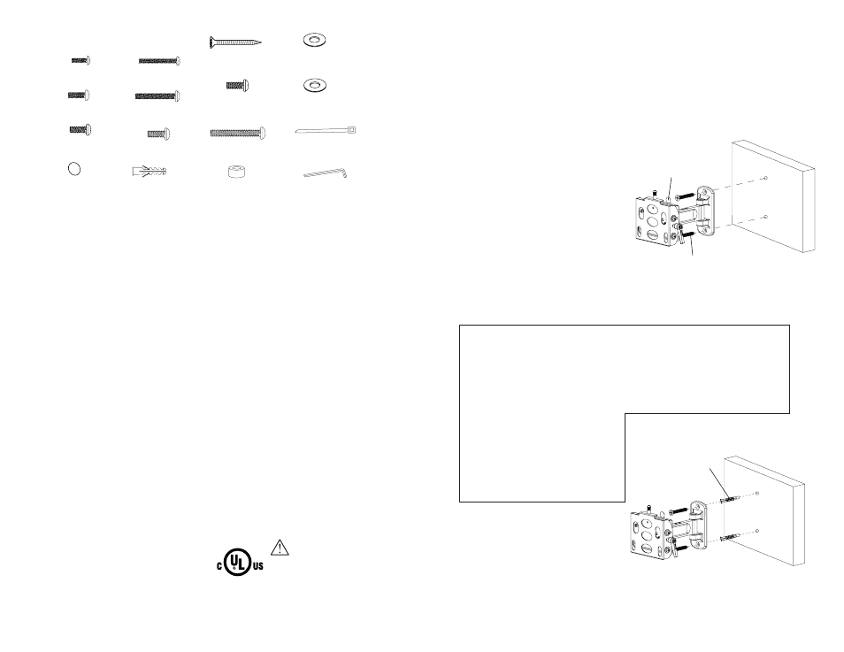
For Mounting on a Stud Wall (Fig 1)
a. Pre-drill two holes into stud using a 3/16” drill bit.
Be sure to drill into the center of the studs.
b. Insert two Wood Screws into holes through
the Wall Plate and tighten down. Be sure the
Wall Arm Assembly is mounted with the
key slots pointing upwards
WARNING: Tighten screws so that the
Wall Plate is firmly attached, but
do not over tighten. Over tightening
can damage the screws, greatly
reducing their holding strength.
c. (Optional) Attach Screw Covers over
head of screws.
For Mounting on a Concrete Wall (Fig 2)
a. Pre-drill two holes into concrete using 5/16” drill bits. Insert Concrete Wall
Anchors and tap in with hammer, if necessary.
WARNING: When installing Wall Arm Assembly on cinder block, verify first
that you have a minimum of 1-3/8” of concrete thickness to be used for the
Concrete Wall Anchors. Do not drill into mortar joints! Be sure to mount in
a solid part of the block, generally 1”minimum from the side of the block.
Cinder block must meet ASTM C-90 specifications. It is suggested that a
standard electric drill on slow setting is used to drill the hole instead of a
hammer drill to avoid breaking out the back of the hole when entering
a void or cavity.
Concrete must be 2000 psi density
minimum. Lighter density concrete
may not hold concrete anchor.
Make sure that the supporting surface
will safely support the combined load
of the equipment and all attached
hardware and components.
b. Insert two Wood Screws into the
Wall Anchors through the Wall
Plate. Be sure the Wall Arm
Assembly is mounted with the
key slots pointing upwards.
WARNING: Tighten screws so that wall plate is firmly attached, but do not
over tighten. Over tightening can damage the screws, greatly reducing their
holding strength.
c. (Optional) Attach Screw Covers over head of screw.
HARDWARE KIT
M4 x 12mm Philips
Head Screw (x4)
M6 x 12mm Philips
Head Screw (x4)
M8 x 14mm Philips
Head Screw (x4)
4” Wire Tie (x4)
Allen Wrench, 4mm (x1)
Concrete Wall Anchor (x2)
Screw Cover (x2)
M4 x 30mm Philips
Head Screw (x4)
M5 x 30mm Philips
Head Screw (x4)
M6 x 30mm Phillips
Head Screw (x4)
M5 x 12mm Philips
Head Screw (x4)
M6 x 20mm Philips
Head Screw (x4)
M6 (17.8 x 6.5 x 1.5mm)
Metal Washer (x4)
TOOLS REQUIRED
• Power Drill
• 3/16” (5mm) Drill Bit
• 5/16” (8mm) Masonry Bit
• Phillips Head Screw Driver
• Level
Fig 2
# 14x2.5” Philips
Wood Screw (x2)
Concrete Anchor
Screw Cover
Wood Screw
Fig 1
M8 (20.5 x 8.5 x 2mm)
Metal Washer (x8)
M4/M5/M6 spacer:
12mm (x4)
CAUTION:
This wall mount is intended
for use only with the maximum
weight of 80 lbs (36.4kg).