Installation, Caution, For mounting on a concrete wall – Staub Electronics SM-F-L STRONG - LARGE FIXED MOUNT FOR 36-60 FLAT-PANEL TVS User Manual
Page 2: Step 2: mount arms to television, Correct, Incorrect, Warnings, Specifications, Box contents, Tools required
INSTALLATION:
Step 1: Mounting the Wall Bracket Assembly
For Mounting on a Stud Wall
a. Pre-drill holes into two wood studs using a 1/4” drill bit.
Be sure to drill into the center of the studs at least
2-1/2” deep. The use of a stud finder is highly
recommended.
b. Insert four flange bolts (V) into holes through the Wall
Plate and tighten down.
WARNING:
Tighten bolts so that wall plate is firmly
attached, but do not overtighten. Overtightening
can damage the bolts, greatly reducing their
holding strength.
For Mounting on a Concrete Wall
a. Pre-drill holes into concrete using 5/16” drill bits to a
depth of 2 1/2”. Insert concrete wall anchors (U)
and tap in-with hammer, if necessary (Figures 2 & 3).
WARNING:
When installing wall arm assembly on
cinder block, verify first that you have a minimum
of 1-3/8” of concrete thickness to be used for the
concrete anchors. Do not drill into mortar joints! Be
sure to mount in a solid part of the block, generally
1”minimum from the side of the block. Cinder block
must meet ASTM C-90 specifications. It is suggested that
a standard electric drill on slow setting is used to drill the
hole instead of a hammer drill to avoid breaking out the
back of the hole when entering a void or cavity.
Concrete must be 2000 psi density minimum.
Lighter density concrete may not hold concrete
anchor
.
Make sure that the supporting surface will safely
support the combined load of the equipment and
all attached hardware and components.
b. Insert four flange bolts (V) into the wall anchors
through the Wall Plate.
Tighten all bolts.
WARNING:
Tighten bolts so that wall plate is firmly
attached, but do not overtighten. Overtightening
can damage the bolts, greatly reducing their
holding strength.
Step 2: Mount Arms to television
a. Determine the diameter of the screw (parts A through
P) your TV requires by carefully trying to hand-thread
one into the threaded insert on the rear of the TV. If
there is any resistance, stop immediately.
b. Spacers are commonly needed on televisions with
curved backs or recessed screw inserts. The screw
will thread through the appropriate washer (D, H, L,
or P), any spacer needed (Q, R, or S) and the arms
into the TV.
c. Ensure the arms are installed flat side to television
and are square to each other after all screws have
been installed (Figure 4).
Correct
concrete
concrete
plaster/
drywall
plaster/
drywall
Incorrect
Cuta
w
ay
Vie
w
Figure 2
Drill holes and
insert anchors.
Place wall arm
assembly plate
over anchor and
secure with
flange bolt.
Tighten all
flange bolts.
Wall Arm
Concrete
Wall
Flange Bolt
Figure 3
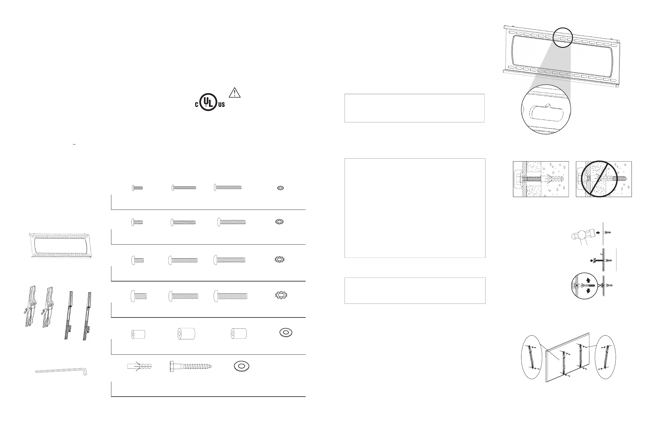
TIP: To assist in
installation, the
wall bracket features
a screw slot for
temporary hanging
of the bracket.
NS
WARNINGS:
• Installation by a qualified professional is highly recommended for this product.
• Do not begin installation until you have thoroughly read and understand these instructions.
• This mount supports displays from 36” to 60”, VESA 700x500, and a maximum load of 165 lbs (75 kg).
• Ensure the mounting wall will safely support four times the combined weight of the Mount
and display panel.
• Under no circumstances should this product be mounted to metal studs.
• The manufacturer does not accept responsibility for incorrect installation.
SPECIFICATIONS:
• Maximum Load: 165 lbs. (75 kg)
• Display Size: 36” to 60”
• Forward Tilt Range: - 8° /+ 13°
• Horizontal Tilt Range: +5°
BOX CONTENTS:
• Wall Plate (1)
• Arm left (1)
• Arm right (1)
TOOLS REQUIRED:
• Power Drill
• 5/16” and 1/4” Drill Bit
• Phillips Head Screw Driver
• Level
• Socket Wrench
with 7/16” Socket head
PACKAGE CONTENTS:
(X) Allen Key (x1)
Arms
(With SM-T-L)
Wall Plate
Arms
(With SM-F-L)
HARDWARE KIT
(Q) M10x80
Lag Bolt (x4)
Pkg 3
Pkg 2
Pkg 1
Pkg 4
Pkg 5
Pkg 6
CAUTION:
This wall mount is intended
for use only with the
maximum weight of
165 lbs (75kg).
Figure 1
Figure 4
(A) M4x12 Bolt (x4)
(E) M5x12 Bolt (x4)
(I) M6x12 Bolt (x4)
(M) M8x16 Bolt (x4)
(Q) Small Spacer (x4)
(U) Concrete
Anchor (x6)
(B) M4x20 Bolt (x4)
(F) M5x20 Bolt (x4)
(J) M6x20 Bolt (x4)
(N) M8x25 Bolt (x4)
(R) Large Spacer (x4)
(V) M8x63
Flange Bolt (x6)
(C) M4x30 Bolt (x4)
(G) M5x30 Bolt (x4)
(K) M6x35 Bolt (x4)
(O) M8x40 Bolt (x4)
(S) M8x18x10 Spacer (x4)
(W) Lag Bolt
Washer (x6)
(D) M4 Lock Washer (x4)
(H) M5 Lock Washer (x4)
(L) M6 Lock Washer (x4)
(P) M8 Lock Washer (x4)
(T) M6 Washer (x4)