Installation, For mounting on a concrete wall, Correct – Staub Electronics SM-CS-ART1-M STRONG - CONTRACTOR SERIES ARTICULATING MOUNT FOR 26 - 47 FLAT PANEL TVS User Manual
Page 2: Incorrect
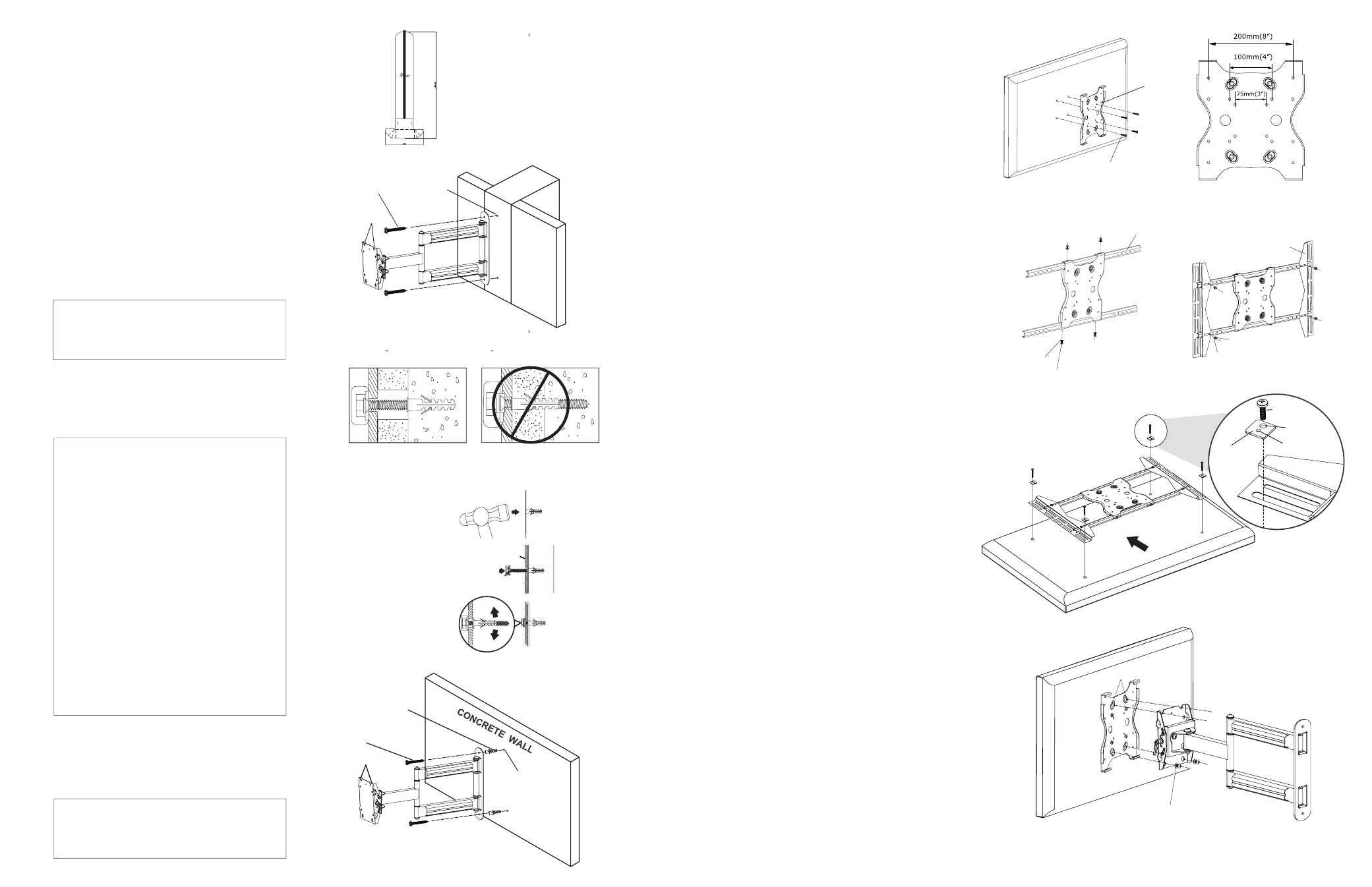
INSTALLATION:
Step 1: Use Template to mark
Mounting Hole locations
for flange bolts
Step 2: Mounting the Wall
Arm Assembly
For Mounting on a Stud Wall
a. Pre-drill holes into studs using a 1/4” drill
bit. Be sure to drill into the center of the
studs. The use of a stud finder is highly
recommended.
b. Insert two flange bolts (M) into holes through
the wall plate and tighten down.
Be sure the
Wall Arm Assembly is mounted with the key
slots pointing upwards (See Figure 1).
WARNING:
Tighten bolts so that wall plate
is firmly attached, but do not overtighten.
Overtightening can damage the bolts,
greatly reducing their holding strength.
For Mounting on a Concrete Wall
a. Pre-drill holes into concrete using 5/16” drill
bits. Insert concrete wall anchors (Q) and
tap in with hammer, if necessary (Figure 2).
WARNING:
When installing wall arm
assembly on cinder block, verify first that
you have a minimum of 1-3/8” of concrete
thickness to be used for the concrete
anchors. Do not drill into mortar joints! Be
sure to mount in a solid part of the block,
generally 1”minimum from the side of the
block. Cinder block must meet ASTM C-90
specifications. It is suggested that a standard
electric drill on slow setting is used to drill the
hole instead of a hammer drill to avoid
breaking out the back of the hole when
entering a void or cavity.
Concrete must be 2000 psi density
minimum. Lighter density concrete
may not hold concrete anchor
.
Make sure that the supporting surface
will safely support the combined load
of the equipment and all attached
hardware and components.
b. Insert two flange bolts (M) into the wall
anchors through the wall plate.
Be sure
the Wall Arm Assembly is mounted with
the key slots pointing upwards (Figures 3 & 4).
WARNING:
Tighten bolts so that wall plate
is firmly attached, but do not overtighten.
Overtightening can damage the bolts,
greatly reducing their holding strength.
Drill holes and
insert anchors.
Step 3: Attaching the Adapter Plate
to the Display
For up to VESA 200x200- Small Displays
a. Only the adapter plate is needed. Attach
the adapter plate to the display using M4,
M5, or M6 screws. For displays with a hole
pattern in a pocket, spacers (U) go between
adapter plate and display (See Figure 5).
For up to VESA 400x600- Large Displays
a. Align the holes in the adapter bars with the
adapter plate and attach using four M6x12
(N) screws and four 6mm metal washers (R)
(See Figure 7).
b. Slide the Adapter Brackets onto assembled
Adapter Bars. Place the assembled
Adapter Plate on the back of the display
with one Adapter Bracket aligned with
mounting holes of display. Then, slide the
other Adapter Bracket in or out until it aligns
with the second set of mounting holes. The
Adapter Plate should be horizontally
centered on the back of the display
(See Figure 8).
c. Attach the Assembled Adapter Plate to
screen using the suitable screws (See
Figure 9). For displays with a hole
pattern in a pocket, spacers (U) go between
adapter plate and display.
Step 4: Attaching the Adapter Plate
with Display to Wall Arm
Assembly
For up to VESA 200x200- Small Displays
a. Insert two M8x12mm (O) screws and two
8mm metal washers (S) into top two holes
of Adapter Plate. Leave approximately 1/4”
of exposed thread (Do NOT tighten fully).
b. Lift the display and hook it over the
mounting head by lowering the exposed
portion of the top screws into the open key
slots of Wall Arm Assembly mounting head.
c. Once in position, attach the bottom two
M8x12mm screws (O) and 8mm metal
washers (S) to secure the Adapter Plate
to the mounting head using the Allen
Key (T) to tighten down all M8 screws
(See Figure 10).
Place wall arm
assembly plate
over anchor and
secure with
flange bolt.
Tighten all
flange bolts.
Correct
concrete
concrete
plaster/
drywall
plaster/
drywall
Incorrect
Cuta
w
ay
Vie
w
Wall Arm
Concrete
Wall
Flange Bolt
1/4” holes
Flange
Bolt (M)
Template
Key Slots
Adapter Panel
M4, M5, or
M6 Screw
Adapter Bar
Adapter Bracket
6mm Metal
Washer (R)
Metal Washer (R)
M6x12 Screw (N)
M6x12 Screw (N)
Top of
Display
Mounting
Screw
M6&M8
Washer Hole
M4&M5
Washer Hole
Square
Washer
Mounting
Screw
M6 or M8
Washer Hole
M4 or M5
Washer Hole
Square
Washer (P)
Figure 1
Figure 2
Figure 3
Masonry Wall
Anchor (Q)
Flange Bolt (M)
Key Slots
5/16” holes
Figure 4
Figure 5
Figure 7
Figure 8
Figure 9
Figure 6
M8x12mm
Screw (O)
Top Screw
8mm Metal
Washer (S)
Figure 10
Adapter Plate