Staub Electronics SM-CEILING-SCA-WH STRONG - SUSPENDED CEILING TILE ADAPTER PLATE User Manual
Page 2
WARNINGS
• Installation by a qualified professional is highly recommended.
• Do not begin installation until these instructions have been thoroughly
read and understood.
• This ceiling plate supports a maximum load of 100 lbs (45.5 kg).
• The manufacturer does not accept responsibility for incorrect installation.
TOOLS REQUIRED
• Power Drill
• 5/32” (4mm) Drill bit
• 1/4” (6mm) Masonry Bit
• 13/32” Socket Head Wrench
INSTALLATION INSTRUCTIONS
Important Pre-Assembly Information:
The Ceiling Tray is designed to fit above a 24” (610 mm) x 24” (610mm) or 24” (610mm)
x 48” (1220mm) conventional suspended ceiling. Ceiling runners should have a “T”
cross-section and a minimum height of 1.5” (38 mm).
For certain installations, ceiling anchors may need to be installed (Step 3)
before the ceiling tray (Step 1).
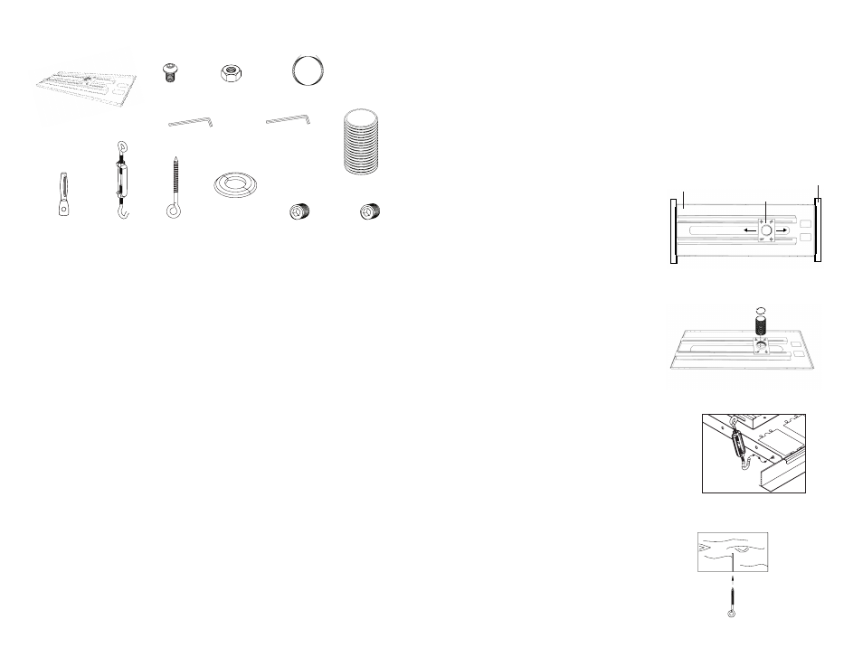
Step 1: Install the Ceiling Tray
a. Place the Ceiling Tray in the grid above
a 24” x 24” or 24” x 48” false ceiling tile
so that lip of Ceiling Tray rests on
ceiling runners (Fig 1).
b. Slide Collar Mount Plate to desired position.
Using hole in Collar Mount Plate, mark the
ceiling tile where the hole will be cut.
Remove Ceiling Tray and cut out a 2.25”
hole in ceiling tile. Slide Collar Mount
Plate back into position over cut hole
and tighten all Wing Nuts.
Step 2: Install the Flush Mount Tube
a. From the top, thread the Flush Mount Tube
through Retaining Collar in Ceiling Tray and
through the Ceiling Tile (Fig 2). Tighten the
Set Screw.
b. Add Eschutchen ring for a more finished look.
Step 3: Install the Wire Supports
a. Insert Turnbuckle hooks into four corners of Ceiling
Tray (Fig 3).
b. Cut Tie Wire into four pieces of equal length and
insert wires through the ends of the Turnbuckles.
c. Twist each wire around itself several times
(minimum of 6-8 times recommended)
as tightly as possible.
d. Drill holes for four Ceiling Anchors
based on material:
Wood Joists or Beams:
Drill 5/32” (4 mm) diameter
holes 2” (51 mm) deep.
PARTS INCLUDED
Allen Wrench, 2.5mm,
Security/Non-Security (x1)
Allen Wrench, 4mm (x1)
M5 x 5mm Set Screw,
Security (x2)
M5 x 5mm
Set Screw (x2)
Escutcheon (x1)
Tie Wire, 20’ (x1)
Eye Bolt (x4)
Turnbuckle (x4)
Concrete
Anchor (x4)
1/4”-20 Nut (x4)
Flush Mount
Tube (x1)
1/4”-20 x 3/8”
Screw (x4)
Ceiling Tray (x1)
Fig 1
Fig 2
Fig 3
Fig 4
Ceiling
Runners
Ceiling
Tray
Collar Mount
(Continued on back)