Staub Electronics SM-CEILING-CT-2X2-WH STRONG - 2X2 SUSPENDED CEILING TILE REPLACEMENT User Manual
Page 2
WARNINGS
• Installation by a qualified professional is highly recommended.
• Do not begin installation until these instructions have been thoroughly
read and understood.
• This ceiling plate supports a maximum load of 90 lbs (40.82 kg).
• The manufacturer does not accept responsibility for incorrect installation.
TOOLS REQUIRED
• Power Drill
• 5/32” (4mm) Drill bit
• 1/4” (6mm) Masonry Bit
• 13/32” Socket Head Wrench
INSTALLATION INSTRUCTIONS
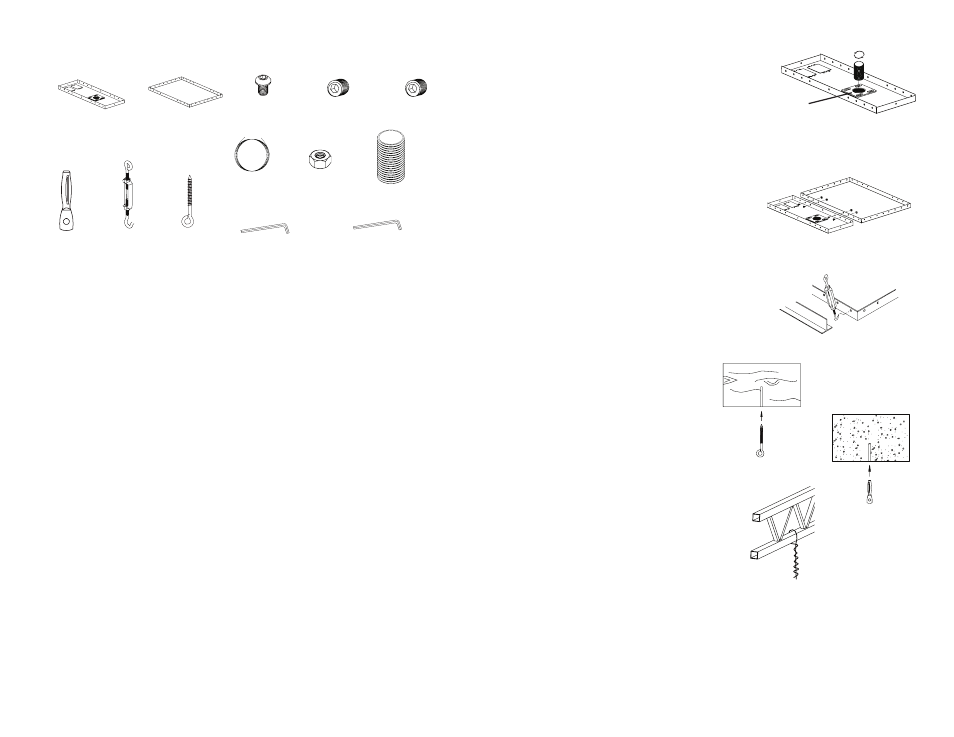
Step 1: Install the Flush Mount Tube
a. From the top, thread the Flush Mount Tube
through Retaining Collar in Ceiling Tray.
Step 2: Install the Ceiling and Filler Trays
a. Place Ceiling Tray into 24” (610 mm) x 24” (610 mm)
opening in ceiling (in place of a ceiling tile) with Retaining
Collar to the right or left.
b. Place Filler Tray into gap.
c. Attach Ceiling Tray to Filler Tray using four Screws
and four Nuts.
Step 3: Install the Wire Supports
a. Insert Turnbuckle hooks into four corners of Ceiling Tray.
b. Cut Tie Wire into four pieces of equal length and
insert wires through the ends of the Turnbuckles.
c. Twist each wire around itself several times
(minimum of 6-8 times recommended)
as tightly as possible.
d. Drill holes for four Ceiling Anchors
based on material:
Wood Joists or Beams:
Drill 5/32” (4 mm) diameter
holes 2” (51 mm) deep.
Fully insert Eye Bolts (Fig 4).
Solid Concrete:
Drill 1/4” (6 mm) diameter
holes 1.5” (38 mm) deep.
Hammer in Concrete Anchors (Fig 5).
Truss Ceiling:
No anchor required. After attaching
Tie Wire to Turnbuckle, loop upper end
around ceiling truss. Pull Tie Wire tight
and twist it around itself several times
(minimum of 6-8 times recommended)
as tightly as possible (Fig 6).
Position the holes so when the tie wires are
attached and taut, the optimal angle is 15°.
Unit may be mounted at an angle up to
45° if necessary.
e. Pull Tie Wires tight and attach to ends of ceiling anchors. Twist each wire around
itself several times (minimum of 6-8 times recommended) as tightly as possible.
The weight of the Ceiling Tray should be supported by the Tie Wires.
Note: 20’ (6.1 m) of Tie Wire is provided. If space between the true ceiling and
suspended ceiling is more than 36” (914 mm), additional wire (12 gauge annealed,
steel, black) will be needed.
DO NOT extend two wires together - use one continuous wire.
PARTS INCLUDED
Allen Wrench, 2.5mm,
Security/Non-Security (x1)
Allen Wrench, 4mm (x1)
Tie Wire, 20’ (x1)
Eye Bolt (x4)
Turnbuckle (x4)
Concrete
Anchor (x4)
1/4”-20 Nut (x4)
Flush Mount
Tube (x1)
Fig 1
Fig 2
1/4”-20 x 3/8”
Screw (x4)
Ceiling Tray (x1)
Filler Tray (x1)
Fig 3
Fig 4
Fig 5
Fig 6
Retaining
Collar
M5 x 5mm Set Screw,
Security (x2)
M5 x 5mm
Set Screw (x2)