KB Electronics KBMM-225D User Manual
Page 18
6.9
DC Tach-Generator Connection – A DC tach-generator
can be used for load regulation of 1% of the set speed.
Note: Jumper J2 must be set to the “T” position for
tach-generator operation. Connect the tach-generator
as follows.
Application Notes – 1. The tach-generator input circuit is
designed for a 7 Volt or 50 Volt per 1000 RPM DC tach-
generator used with an 1800 RPM motor. 2. Initially set the
IR Comp Trimpot fully counterclockwise. Once the tach-
generator is connected, the IR Comp Trimpot may be
increased for additional speed stabilization.
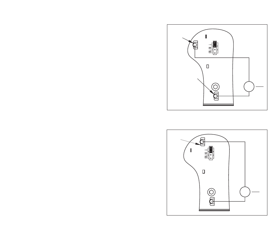
6.9.1 Seven (7) Volt per 1000 RPM Tach-Generator –
Connect the tach-generator positive lead (+) to
Terminal “T” and the negative lead (-) to Terminal
“I2”, as shown in Figure 8.
6.9.2 Fifty (50) Volt per 1000 RPM Tach-Generator –
Connect the tach-generator positive lead (+) to
Terminal “B” and the negative lead (-) to Terminal
“I2”, as shown in Figure 9.
6.9.3 Other Tach-Generator Voltages – The tach-gener-
ator input circuit is designed for a 7 Volt or 50 Volt
per 1000 RPM DC tach-generator used with an
1800 RPM motor. For a tach-generator other than 7
Volts or 50 Volts per 1000 RPM, or for a motor
other than 1800 RPM, an external 1/2 Watt resistor
(RT) must be installed. Install RT in series with the
18
B
PWR ON
I2
T
DC Tach-Generator
-
+
7V
G
1000
Terminal "T"
Terminal "I2"
J2
FIGURE 8 – DC TACH-GENERATOR CONNECTION
(7 VOLTS PER 1000 RPM)
B
PWR ON
I2
T
1000
G
50V
DC Tach-Generator
-
+
Terminal "B"
J2
FIGURE 9 – DC TACH-GENERATOR CONNECTION
(50 VOLTS PER 1000 RPM)