KB Electronics KBMM-225D User Manual
Page 11
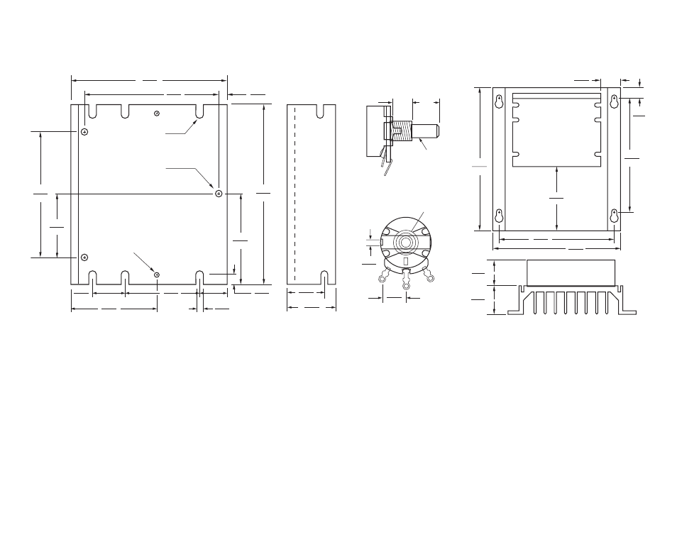
CONTROL
MOUNTING "D"
2 SLOTS
POTENTIOMETER
(SUPPLIED)
MAIN SPEED
OPTIONAL AUXILIARY HEAT SINK
.95
24.1
1.25
31.8
.50
12.7
.98
24.9
5.63
143
3.11
(79.0)
5.63
142.9
6.25
159
1.25
31.8
1.38
34.9
7.00
178
1
ANTI-
ROTATION
PIN
3/8-32
BUSHING
3/8"
SHAFT
1/4" ROUND
1/2"
P
2
P
3
P
.44
11.1
.13
3.1
MOUNTING "B"
TAPPED 10-32
(3 PLACES)
FUSE HOLDER & FINGER-SAFE
COVER MOUNTING HOLES
TAPPED 6-32
(2 PLACES)
MOUNTING "A"
6 SLOTS
3.64
92.5
3.10
78.5
.22
5.6
4.30
109
2.15
54.6
.25
6.4
.18
4.6
.64
16.3
1.75
44.5
1.75
44.5
.75
19.1
1.50
38.1
3.00
76.2
11
4
APPLICATION INFORMATION
4.1
Motor Type – The control is designed for permanent magnet (PM) and Shunt Wound DC motors. Controls
operated on 115 Volt AC line input are designed for 90 Volt SCR rated motors. Controls operated on 230 Volt
AC line input are designed for 180 and 90 Volt SCR rated motors. Use of motors with higher rated voltage will
result in a reduction of the available maximum speed. Also, if the motor is not an SCR rated type, the actual
AC line current at full load and full speed should not exceed the motor’s DC nameplate current rating.
4.2
Torque Requirements – The motor selected for the application must be capable of supplying the necessary
torque. In order to ensure the motor is not overloaded, a DC ammeter should be connected in series with
the armature. Be sure the current under full load does not exceed the motor nameplate rating.
FIGURE 2 – MECHANICAL SPECIFICATIONS (Inches/mm)