KB Electronics KBMM-225D User Manual
Page 15
6.5
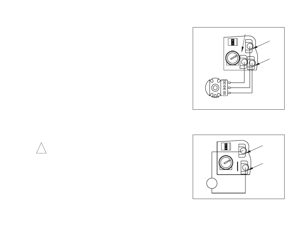
Remote Main Speed Potentiometer Connection – The control
is supplied with a Main Speed Potentiometer to control motor
speed. Wire the low side of the potentiometer to Terminal “P1”.
Wire the wiper of the potentiometer to Terminal “P2”. Wire the
high side of the potentiometer to Terminal “P3”. See Figure 3.
6.6
Voltage Following Connection – An isolated 0 - 9 Volt DC ana-
log signal input can be used to control motor speed in lieu of the
Main Speed Potentiometer. The control output voltage will linearly
follow the analog signal input. The signal input must be isolat-
ed from the AC line. Connect the signal input positive lead (+) to
Terminal “P2” and the negative lead (-) to Terminal “P1”, as
shown in Figure 4. The source impedance of the signal input
should be 10 k
Ω or less. The MAX Trimpot is not operational in
voltage following mode. Use the MIN trimpot to set an initial value
of input signal. If necessary, use auxiliary trimpots to scale and/or
limit the input voltage.
CAUTION! Do not earth ground any input terminals.
Notes: 1. If an isolated signal input is not available, or if using a
4 - 20 mA DC signal input, install the optional plug-on SI-6 Signal
Isolator (Part No. 9444). This will also allow direct connections to
process controllers and microprocessors. 2. If multiple follower
motors are to be controlled from a single lead motor or a single
Main Speed Potentiometer, install the optional KBSI-240D Signal
Isolator (Part No. 9431). 3. Terminal “F-” may be used in lieu of Terminal “P1”.
15
(Front View)
Main Speed Potentiometer
EN
CONN1
P3
MAX
P1
P2
High
Wiper
Low
Terminal "P3"
Terminal "P1"
Terminal "P2"
FIGURE 3 – REMOTE MAIN SPEED
POTENTIOMETER CONNECTION
CONN1
P2
MAX
EN
P3
P1
V
-
+
0 - 9 Volts DC
(Isolated)
Terminal "P1"
Terminal "P2"
FIGURE 4 – VOLTAGE FOLLOWING
CONNECTION
!