KB Electronics KBMM-225D User Manual
Page 17
Volts DC). If the MIN
Trimpot is set to other
than 0 Volts DC, the
motor will run at that
speed when the
switch or contact is
opened. An open col-
lector (PNP) can be
wired in lieu of a
switch or contact.
Note: The decelera-
tion time can only be
made longer than the
normal coasting time
of the load.
6.8
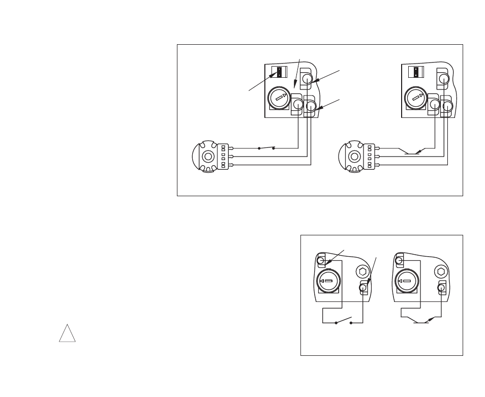
Inhibit Circuit Connection – The control can be stopped
and started with an Inhibit circuit (close to stop, open to run).
Wire the switch or contact to Terminals “I1” and “I2”, as
shown in Figure 7. When the switch or contact is closed, the
motor will coast to stop. When the switch or contact is
opened, the motor will accelerate to the Main Speed
Potentiometer setting. An open collector (NPN) can be wired
in lieu of a switch or contact.
WARNING! The Inhibit Circuit is never to be used
as a Safety Disconnect since it is not fail-safe. Use
only the AC line for this purpose.
17
CONN1
Enable Switch or Contact
This jumper must
Main Speed Potentiometer
(Front View)
(Close to Run)
Low
High
Wiper
(Open to Stop)
be installed
MAX
EN
Terminal "P1"
Main Speed Potentiometer
(Front View)
(On to Run)
Low
High
Wiper
Open Collector
(Off to Stop)
MAX
CONN1
Terminal "P3"
Terminal "P2"
P3
P1
P2
EN
P3
P1
P2
FIGURE 6 – ENABLE SWITCH OR CONTACT WIRED TO THE
MAIN SPEED POTENTIOMETER
!
MIN
I1
I2
(Close to Stop)
Inhibit Switch or Contact
(Open to Run)
MIN
I2
I1
(On to Stop)
(Off to Run)
Open Collector
Terminal "I1"
Terminal "I2"
FIGURE 7 – INHIBIT SWITCH OR CONTACT
WIRED TO THE INHIBIT TERMINALS