KB Electronics KBMM-225D User Manual
Page 13
Important Application Note: To avoid erratic operation, do not bundle the AC line and motor wires with
wires from signal following, start/stop contacts, or any other signal wires. Also, do not bundle motor
wires from multiple controls in the same conduit. Use shielded cables on all signal wiring over 12” (30
cm). The shield should be earth grounded on the control side only. Wire the control in accordance with
the National Electrical Code requirements and other local codes that may apply.
13
6.1
AC Line Connection – Wire the AC line to Terminals “L1” (Line Fuse) and “L2”, as shown in Figure 1, on
page 10. If one of the AC line inputs is a neutral (N), wire it to Terminal “L2”.
CAUTION! The rated AC line voltage (115, 208/230) of the control must match the actual AC line
input voltage. See Section 7.1, on page 19.
Model KBMM-125 operates on 115 Volt AC line input only. Model KBMM-225 operates on 208/230 Volt AC
line input only. Model KBMM-225D operates on 115 Volt AC line input when Jumper J1 is set to the “115”
position and operates on 208/230 Volt AC line input when Jumper J1 is set to the “230” position.
AC Line On/Off Switch – To remove power to the control, a separate AC line switch should be used. Use a
single pole switch for hot and neutral AC supply lines and a double pole switch for 2-hot AC supply lines.
This switch can also be used as a “Safety Disconnect”.
6.2
Ground Connection – Connect the ground wire (earth) to the control chassis.
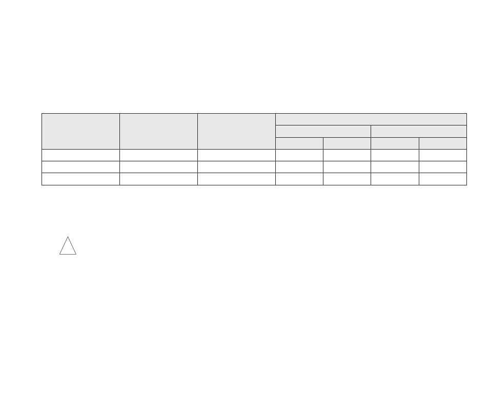
Maximum Motor Current
(Amps DC)
90 - 130 Volt DC Motors
(Maximum HP)
180 Volt DC Motors
(Maximum HP)
Minimum Wire Size (Cu)
Maximum 50 Ft.
Maximum 100 Ft.
AWG
mm
2
AWG
mm
2
6
.5
1
16
1.3
14
2.1
12
1
2
14
2.1
12
3.3
16
1.5
3
12
3.3
12
3.3
TABLE 3 – MINIMUM SUPPLY WIRE SIZE REQUIREMENTS
!