Icspa3-b1n (b2n) h (m) b3h (m), Drawing no, Z-axis cables x-axis, y-axis cables – IAI America NS User Manual
Page 4
X-axis Nut-rotation Type Cartesian Robot – High-precision 3-axis Specification,
Z Base Mount
ICSPA3-B1N (B2N)
H (M) B3H (M)
Drawing No.
Z-axis: ISA, etc.
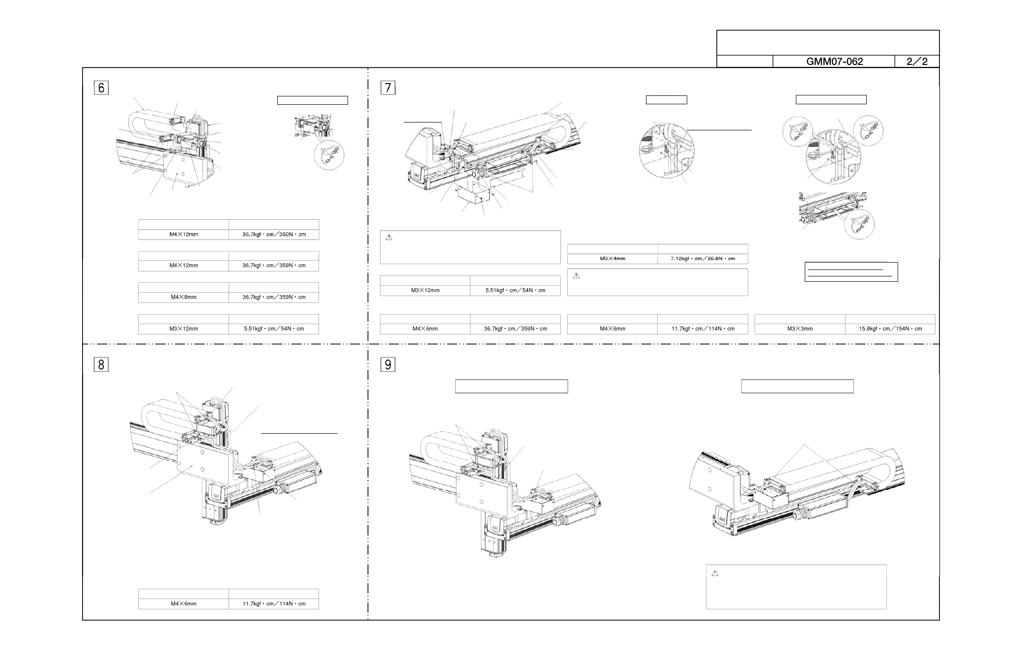
[Installation of cable track 2 [16] on track support bracket [14]]
[Installation of cable track 2 [16] on XY bracket [1]]
[Installation of cable track 2 [16] on track mounting bracket 2 [15]]
[Installation of box cover 2 [18] on connector box 2 [17]]
Caution: The cables for X-axis (axis 1), Y-axis (axis 2) and Z-axis
(axis 3) are placed in tracks. Install each cable correctly.
[Cable markings]
X-axis (axis 1): 1 Y-axis (axis 2): 2 Z-axis (axis 3): 3
[Installation of tie-mount on track mounting bracket 1 [2]]
[Installation of tie-mount in T slot of guide rail [3]]
Tie-mount KR5G5
(by HellermannTyton)
+ hexagonal socket head button bolt M4x6
+ hexagonal nut (1 set)
Install in the T slot of the Y-axis.
[Installation of tie-mount in track mounting bracket 2 [15]]
[Installation of tie-mount on track support bracket [14]]
[Installation of tie-mount in T slot of XY bracket [1]]
[Installation of tie-mount on track mounting bracket 1 [2]]
Z-axis cables
X-axis, Y-axis cables
[16] Cable track 2
Hexagonal socket head bolt M4x8 (2 pcs)
[15] Track mounting bracket 2
Hexagonal
socket head
bolt M4x12
Hexagonal socket head bolt
M4x12
+ hexagonal nut (2 sets)
[14] Track support bracket
[1] XY bracket
[19] Joint cover 2
Hexagonal socket head bolt
M3x12 (8 pcs)
[8] Grommet with film
[18] Box cover 2
[17] Connector box 2
[17] Connector
box 2
Cable connector connection
Connector joint for
ISPA M cable and
PG cable (LS cable)
Hexagonal socket head bolt
Tightening torque
Hexagonal socket head bolt
Tightening torque
Hexagonal socket head bolt
Tightening torque
Hexagonal socket head bolt
Tightening torque
Detail view of A
Tie-mount KR5G5 (by HellermannTyton)
+ hexagonal socket head button bolt M4x6 (1 set)
Cable inside track
[Installation of box cover 1 [6] on connector box 1 [5]]
[Installation of cable guard [10] on XY bracket [1]]
[Installation of metal cover [11] on track mounting bracket 1 [2]]
Caution: Since the hexagonal holes in thin-head bolts are small,
the hexagonal holes may be damaged depending on the
tightening method. Exercise due caution when tightening
thin-head bolts.
Hexagonal socket head button bolt
Place the X-axis cable and
PG cable (LS cable) into
the cable guard [10] and
take them out from the top.
Connector joint for
ISPA M cable and
PG cable (LS cable)
Ground terminal
Connector joint for cable inside track
and controller-actuator cable
[Installation of ground terminal on [1] XY bracket]
[5] Connector box 1
[3] Guide rail
Tie-mount KR5G5
(by HellermannTyton)
+ hexagonal socket head
button bolt M4x6 (1 set)
Hexagonal socket head bolt M3x12 (8 pcs)
[6] Box cover 1
[7] Joint cover 1
[9] Controller-actuator cable with cable fix cap
Thin-head bolt M3x12 (4 pcs)
[11] Metal cover
[10] Cable guard
Hexagonal socket
head bolt M4x6
(2 pcs)
[2] Track mounting bracket 1
Hexagonal socket head bolt
Tightening torque
Hexagonal socket head bolt
Tightening torque
Tightening torque
Tightening torque
Thin-head bolt
Hexagonal socket head bolt
Tightening torque
Hexagonal socket head bolt M3x3
Ground terminal
Cable inside track
Detail view of A
Cable connector connection
[5] Connector box
Connector joint for
NS M cable and
PG cable (LS cable)
[2] Track mounting bracket 1
[4] Cable track 1
Tie-mount KR5G5 (by HellermannTyton)
+ hexagonal socket head button bolt M4x6 (2 sets)
[15] Track mounting bracket 2
[14] Track support bracket
[1] XY bracket
[2] Track mounting bracket 1
Tie-mount KR5G5 (by HellermannTyton)
+ hexagonal socket head button bolt M4x6 (1 set)
Hexagonal socket head button bolt
Tightening torque
Secure the cables using wraps.
Secure the cables using wraps.
Secure the cables using wraps.
Secure the cables using wraps.
Caution: Secure the wires to prevent the cables and connectors
from contacting each axis when the axis is moved over its
entire stroke.
When manually moving the actuator with brake, connect
the controller, supply the power, and then release the brake
release switch (by turning the switch to the RLS side).
Make sure the numbers on the
connectors to be connected match.