Icspa2-b1n (b2n) h (m), Drawing no – IAI America NS User Manual
Page 2
X-axis Nut-rotation Type Cartesian Robot – High-precision 2-axis Specification
ICSPA2-B1N (B2N)
H (M)
Drawing No.
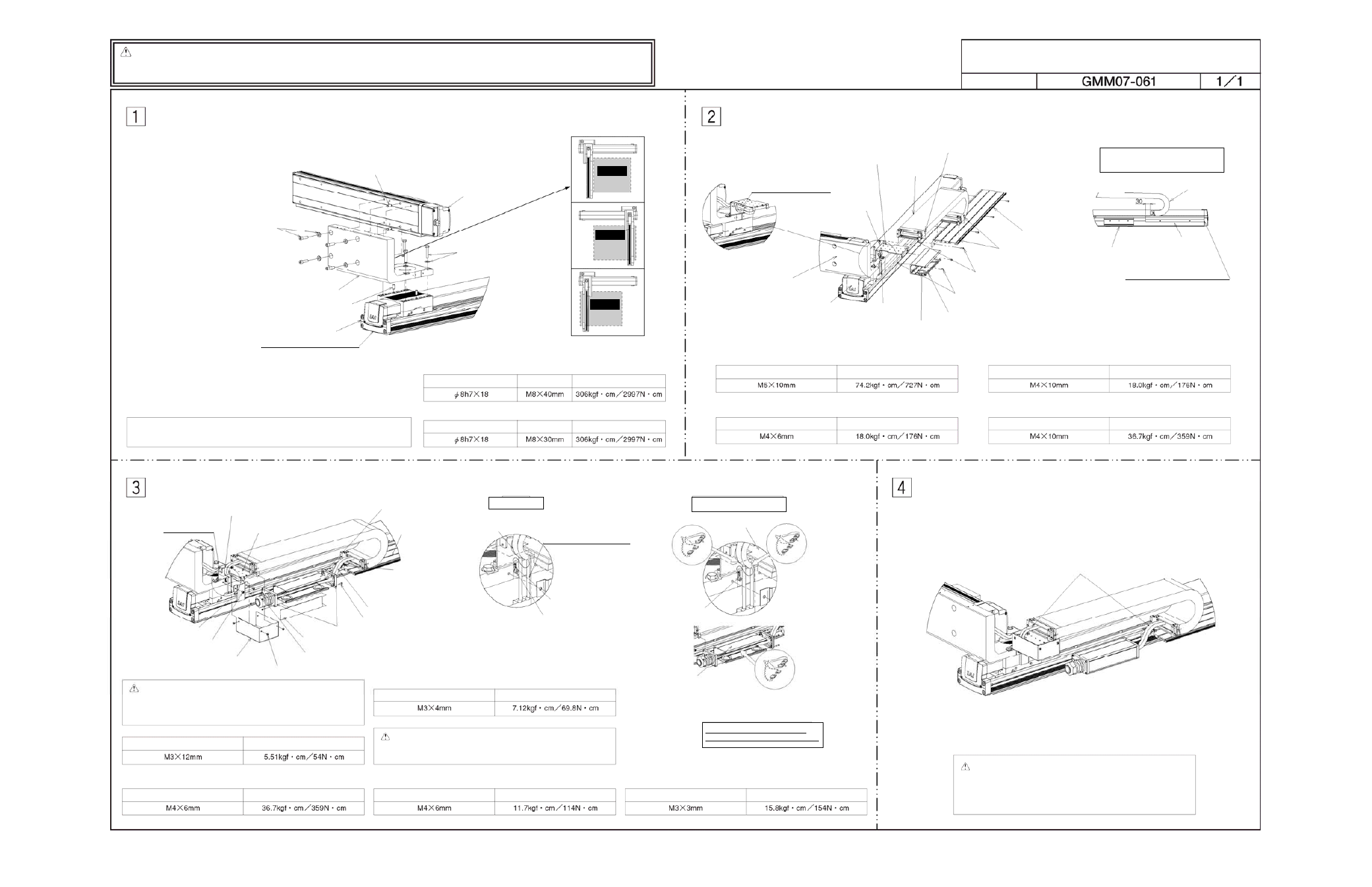
Caution:
Although each part has been chamfered to remove sharp edges, exercise due caution during the
assembly to prevent injury. If necessary, wear gloves or other protective gears.
Exercise due caution during the assembly to prevent pinching of hands and fingers.
[Tools] Allen wrench, spanner wrench
Hexagonal socket head bolt M8x30
+ high-tension washer (4 sets)
X-axis base, reamed-hole side
Hexagonal bolt M8x40
+ high-tension washer (4 sets)
[Installation of X-axis: NS on XY bracket [1]]
[Installation of Y-axis: ISPA on XY bracket [1]]
Parallel pin (2 pcs)
In the case of configuration direction types 2 to 4,
the actuator and bracket directions are different.
Y-axis: ISPA
Parallel pin (1 pc or 2 pcs)
[1] XY bracket
X-axis: NS
Note: To ensure squareness between the X-axis and Y-axis, insert one parallel pin.
Adjust the angle between the X-axis and Y-axis to the right angle, and then
mount the hexagonal bolts.
Parallel pin
Hexagonal bolt
Tightening torque
Parallel pin
Hexagonal socket
head bolt
Tightening torque
Configuration
direction: 2
(Reverse of 1)
(Range of
operation)
Configuration
direction: 3
(Y-axis installed
on opposite side)
(Range of
operation)
Configuration
direction: 4
(Reverse of 3)
(Range of
operation)
Install the grommet with
film [8] onto the Y-axis
actuator cable and
guide the cable through
the hole in the track
mounting bracket [2].
Hexagonal socket head bolt
M4x10
+ hexagonal nut (2 sets)
Flange socket
(hexagonal socket head type) M4x10
+ hexagonal nut (4 sets)
Affixing positions of guide rail [3],
cable track [4] and connector box [5]
Align the guide rail [3] surface
with the end face of the base.
[Installation of track mounting bracket [2] on XY bracket [1]]
[Installation of X-axis: NS side of connector box [5] in T-slot]
[Installation of X-axis: NS side of guide rail [3] in T-slot]
[Installation of cable track [4] on track mounting bracket [2]]
[Installation of guide rail [3] for cable track [4] in T-slot]
Hexagonal socket head bolt
Tightening torque
Tightening torque
Hexagonal socket head bolt
Tightening torque
Tightening torque
Hexagonal socket head bolt
Flange socket (hexagonal socket head type)
Hexagonal socket head bolt M4x10 (2 pcs)
[3] Guide rail
[4] Cable track
[2] Track mounting bracket
Hexagonal socket head bolt
M5x10 (2 pcs)
[5] Connector box
[8] Grommet with film
Hexagonal socket head bolt M4x6
+ hexagonal nut (2 sets)
[8] Grommet with film
[1] XY bracket
X-axis: NS
[5] Connector box
[3] Guide rail
[4] Cable track
Tie-mount KR5G5 (by HellermannTyton)
+ hexagonal socket head button bolt M4x6 (1 set)
Detail view of A
Cable inside track
Caution: The cables for X-axis (axis 1) and Y-axis (axis 2) are
placed in tracks. Install each cable correctly.
[Cable markings]
X-axis (axis 1): 1
Y-axis (axis 2): 2
[Installation of box cover [6] on connector box [5]]
[Installation of cable guard [10] on XY bracket [1]]
[Installation of metal cover [11] on track mounting bracket [2]]
Caution: Since the hexagonal holes in thin-head bolts are small,
the hexagonal holes may be damaged depending on the
tightening method. Exercise due caution when tightening
thin-head bolts.
[Installation of tie-mount on track mounting bracket [2]]
[Installation of tie-mount on guide rail [3]]
Hexagonal socket head button bolt
Place the X-axis cable and
PG cable (LS cable) into
the cable guard [10] and
take them out from the top.
Connector joint for
ISPA M cable and
PG cable (LS cable)
Ground terminal
Connector joint for cable inside track
and controller-actuator cable
[Installation of ground terminal on [1] XY bracket]
Secure the cables using wraps.
Caution: Secure the wires to prevent the cables and connectors
from contacting each axis when the axis is moved over its
entire stroke.
When manually moving the actuator with brake, connect
the controller, supply the power, and then release the brake
release switch (by turning the switch to the RLS side).
* This assembly procedure applies to configuration direction 1. If other configuration direction such as 2, 3 or 4 is used, the actuator and bracket directions vary. However, you can still use this assembly drawing as a reference.
[5] Connector box
[3] Guide rail
Tie-mount KR5G5
(by HellermannTyton)
+ hexagonal socket head
button bolt M4x6 (1 set)
Hexagonal socket head bolt M3x12 (8 pcs)
[6] Box cover
[7] Joint cover
[9] Controller-actuator cable with cable fix cap
Thin-head bolt M3x12 (4 pcs)
[11] Metal cover
[10] Cable guard
Hexagonal socket
head bolt M4x6
(2 pcs)
[2] Track mounting bracket
Hexagonal socket head bolt
Tightening torque
Hexagonal socket head bolt
Tightening torque
Tightening torque
Tightening torque
Thin-head bolt
Hexagonal socket head bolt
Tightening torque
Hexagonal socket head bolt M3x3
Ground terminal
Cable inside track
Detail view of A
Cable connector connection
[5] Connector box
Connector joint for
NS M cable and
PG cable (LS cable)
[2] Track mounting bracket
Make sure the numbers on the
connectors to be connected match.