Harrington Hoists and Cranes Series 3 End Truck User Manual
Page 33
(3) Refer to Figure 3-15, and connect the remaining end of the Drive Shaft to the Joint Shaft
previously installed at the Bearing Support Assembly and fasten.
(4) Slide out the Connecting Shaft from the end of the Drive Shaft nearest the end truck until
the through-bolt holes line up between the Connecting Shaft and Drive Shaft. Fasten the
Drive Shaft to the Connecting Shaft using Bolt A, slotted nut and split pin.
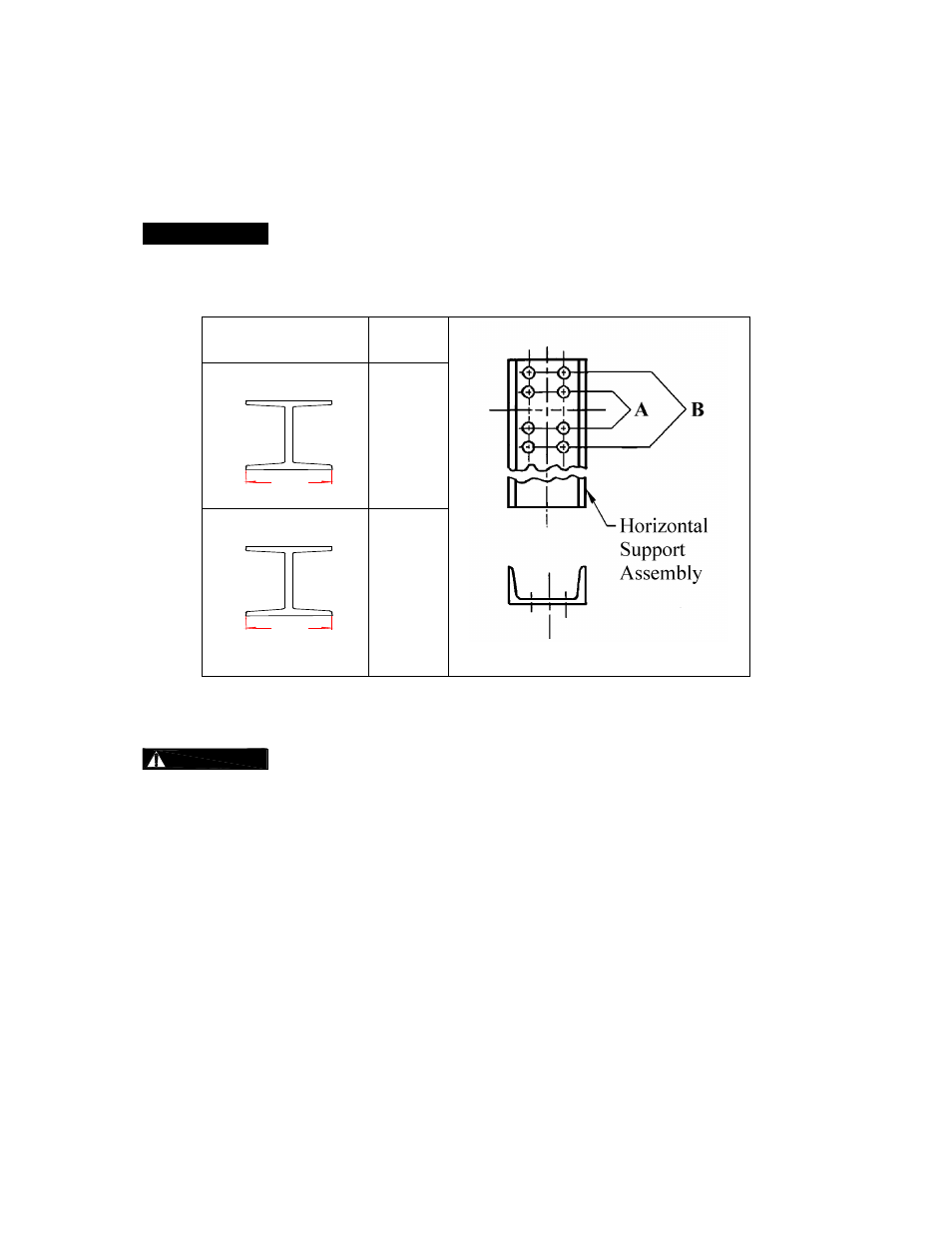
When installing the support arm on the crane bridge beam, note that the support arm
installing pitch varies in each case, shown as in Figure 3-16, depending upon the width of the crane
bridge beam flange.
Flange Width of
Bridge Beam
Bolt
Position
Figure 3-16
3.0 to 5.5 inches
Flange
width
A
5.5 inches and above
Flange
width
B
3.5
Crane Wiring
(MOTORIZED ONLY)
HAZARDOUS ELECTRICAL POWER IS PRESENT IN THE END TRUCK MOTOR,
IN THE SUPPLY OF ELECTRICAL POWER TO THE END TRUCK MOTOR, AND IN THE
CONNECTIONS BETWEEN COMPONENTS.
Before performing ANY wiring installation or maintenance on the equipment, de-energize the electrical
supply to the equipment, and lock and tag the supply device in the de-energized position. Refer to ANSI
Z244.1, “Personnel Protection - Lockout/Tagout of Energy Sources.”
Only trained and competent personnel should install, inspect, and maintain this equipment. ALWAYS
turn off power source or breaker switch to prevent electric shock before beginning the wiring process
Install the crane system electrical wiring as shown on the wiring diagram provided.
33