Harrington Hoists and Cranes Series 3 End Truck User Manual
Page 29
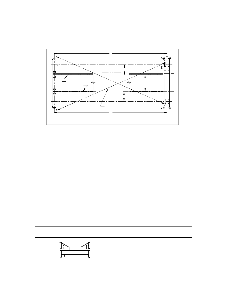
b) Bridge Beams/Rails Alignment - Ensure that the bridge beams/rails conform to the
manufacturer's requirements for the trolley/hoist (e.g. Parallelism, squareness, rail size,
clearances, and gauge).
c) Bridge Beam Coupling to the End Truck - Ensure that the bridge beams are located on the
end trucks so that the center of gravity of the load is transferred to the middle of each end
truck. Verify that C1 = C2.
Y
X
A
B
MAX E LIFT
TROLLEY
(Refer to owner's manual)
Trolley Rails
(Refer to owner's Manual
for specifications)
C1
C2
GAUGE
Figure 3-10
Make adjustments as necessary. Then securely tighten and double nut each fastened
connection of the end truck frame to bridge beam. Refer to tightening torque values of Table 3-1.
3.3.3
Move the crane along the full length of the runway. Check for binding and guide roller clearance
(normal clearance is 5 mm from each guide roller to runway beam flange edge or rail).
3.4
Drive Shafts for Geared End Trucks
3.4.1
General - The drive shaft configuration for your geared crane is shown in Figure 3-11 or Figure 3-
12. Note that the number of Bearing Support Assemblies and Drive Shafts varies according to
the span of the bridge crane system. Refer to Table 3-2.
a) Spans less than or equal to 4.9 meters - single piece drive shaft and no bearing support
assembly.
b) Spans sixteen (16) to thirty-two (32) feet - two piece drive shaft and one bearing support
assembly.
c) Spans greater than thirty-two (32) feet use multiple piece drive shafts with multiple Bearing
Support Assemblies.
Table 3-2
Span
Support Condition
Support
Arms
Up to 4.9
meters
None
29