Figure 5.2: flow chart- a, Aa3 c c1 – Robertshaw SlimZone PREMIER ZONE CONTROL SYSTEM User Manual
Page 23
Are you sure
?
Yes
No
12:00A
Fri
Jan01/99
Auto Mode Fan Auto
Schedule:
Normal
Options Schedule:
Suspended
Programming
12:00A Fri
Jan01/99
System Off Cool Mode Heat Mode Auto Mode EHeat Mode
Schedule:
status
Heat Calls:
# of zones calling
Cool Calls:
# of zones calling
System
mode
Duct
temperatur
e
Outdoor
temperatur
e
Duct
pr
essur
e
MAIN
SCREEN
May select the following:
Fan Auto Fan On
May select the following:
1
1
1
1
1
1
1
1
1
1
1
1
1
2
2
2
2
2
2
2
2
2
2
2
3
3
3
3
3
3
3
3
3
3
3
3
4
4
4
4
4
4
4
4
4
4
4
4
4
4
4
4
4
4
4
4
4
4
4
4
4
4
4
3
HVAC
options
Degrees
C
12
Hour
Clock
Schedule:
Suspended
Until 12:00
Fri
Jan01/99
Program Zone Copy Zone Program 2 Events/day
Copy Zone
#01
To Zone
#02
Do Copy
Copying
Copies the schedule to all
days of the week.
Copies the schedule up to
the day selected, and
increments the days.
Zone # 01
Zone # 01 Set Temperatures Set Schedule
Equipment Zone Module Environmental
Zone #01 Room 76 Heat 68 Cool 70 Auto Mode Calls: Cool
Outdoor
73 Duct
74
Pressure 0.03 in. WC
Bypass - Normal
Zone #01 Exercise Damper Perimeter Heat
Damper
#01
Open
Setup Panel Bypass
For HVAC Techs Only!
Setup
Equipment Test
Locked
Bypass setup Step 06 Wait 30
Temperature Heat
10
Cool
30
Schedule:
Suspended
Permanently
Schedule:
Normal
Set Temperature Heat
10
Morning
Cool
30
Wed
Morning
06:00A
Copy to consecutive Copy to all days
Wed up to Thu
Do Copy
12:00A Fri Jan 01/99
Degrees C Degrees F
May select the following:
Hold for 10 seconds
to unlock scr
een.
Line #4 of the main Scr
een scr
olls the following
information:
(NOTE: Duct and outdoor information ar
e only
displayed if SZEM module connected)
12 Hour Clock 24 Hour Clock
May select the following:
2 Events/day 4 Events/day
May select the following:
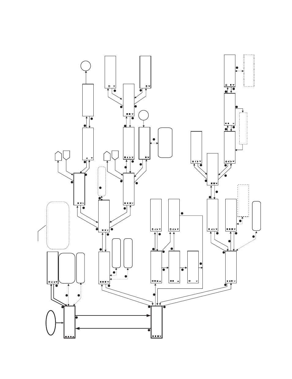
Figure 5.2: Flow Chart- A
Bypass - Open Bypass - Close Bypass - Normal
T
oggles Bypass damper
position to:
Perimeter Heat #01
Off
A
A3
C
C1
B
B