Ransburg, Leps5001 high voltage power supply – Ransburg Voltage Master 2 78789_LEPS5001 User Manual
Page 34
LEPS5001
HIGH VOLTAGE
POWER SUPPLY
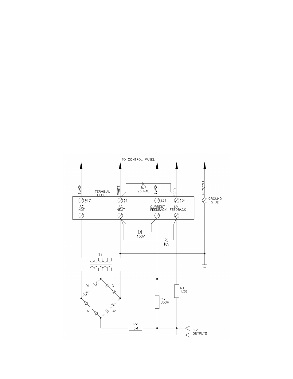
0-120 VAC is supplied to power supply terminals,
wires #1 (neutral) and #17 (hot) from the control
panel through the cable supplied with the power
supply. The input voltage is connected to the pri-
mary of the high voltage transformer, T1. Diode
banks D1 and D2 in conjunction with capacitors
C1 and C2 form a full-wave voltage doubling cir-
cuit. Alternate halves of the AC voltage output,
from the secondary of T1, charge the capacitors.
Since the capacitors are in series, the resulting
Figure 14: Power Supply Schematic
high voltage output is nearly double the peak
voltage from the transformer.
High voltage from the doubling circuit is connect-
ed to an output series resistor, R2, as protection
against output transients. A voltage feedback
signal is supplied through R1, which is connected
to the control panel through wire #34. The ground
return from the isolated transformer secondary,
wire #31, supplies the current feedback signal.
Zener diodes, connected across the terminal
blocks, serve as voltage limiting and transient
suppressors in the event that the KV or current
feedback wires become disconnected from the
control panel. This prevents further damage to
the power supply system in the case of a failure.
Voltage Master 2 - Operation
30
Ransburg
CP-02-02.6