Ransburg, Table 4 - analog control settings, Voltage master 2 - installation – Ransburg Voltage Master 2 78789_LEPS5001 User Manual
Page 24
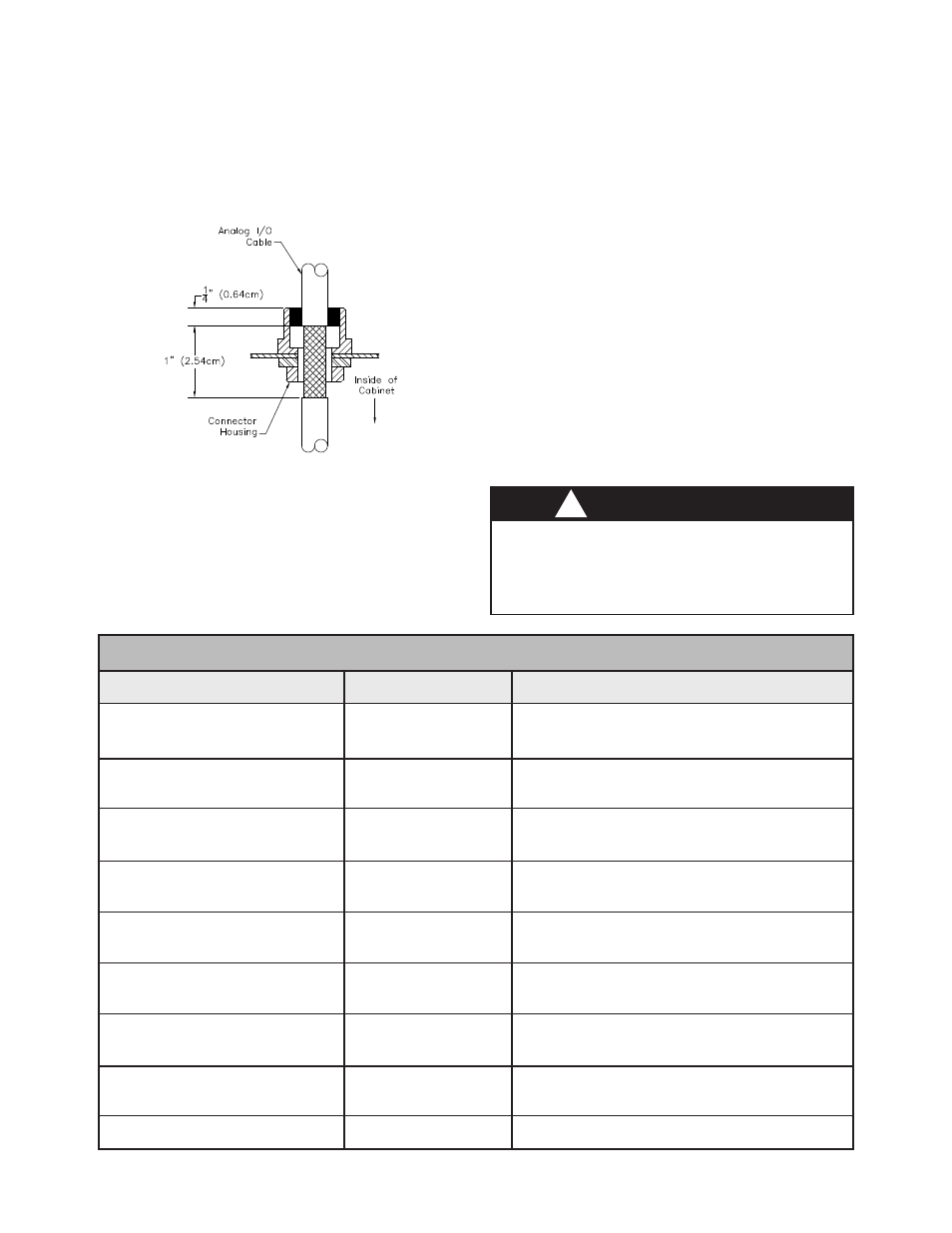
2. Route the desired length of analog I/O cables(s)
through the connector housing(s) and mark 1" span
of cable that passes through connector housing
to be stripped to braid (see Figure 7).
>
Removing the safety cover allows ex-
posure to hazardous potentials. Ensure
AC power is OFF and locked out before
removing the safety cover.
W A R N I N G
!
Figure 7: Stripping of DC I/O Cable
3. Remove cable and strip marked 1" section to
cable braid.
4. Slide the cable grommet hardware onto the
cable in the order shown in Figure 6.
*Motor control board SW1 in left position
(See Figure 8)
Motor control board SW1 in right position
(See Figure 8)
*Master control board JP4, 1-2
(See Figure 9)
Master control board JP4, 2-3
(See Figure 9)
No setting required
No setting required
*Master control board JP5, 1-2
(See Figure 9)
Master control board JP5, 2-3
(See Figure 9)
No setting required
TABLE 4 - ANALOG CONTROL SETTINGS
*KV Setpoint IN
(0-10 V = 0-100 kV)
KV Setpoint IN
(4-20 ma = 0-100 kV)
*OL Setpoint IN
(4-20 ma = 0-1500 µa)
OL Setpoint IN
(0-10 V = 0-1500 µa)
Actual KV OUT
(0-10 V = 0-100 kV)
Actual KV OUT
(4-20 ma = 0-100 kV)
*Actual I OUT
(4-20 ma = 0-2000 µa)
Actual I OUT
(0-10 V = 0-2000 µa)
Earth Ground
Signal
Setting
TB3-58
TB3-59
TB3-63
TB3-63
TB3-60
TB3-65
TB3-64
TB3-64
TB3-GND
Terminal #
* Factory default setting
5. Route the cable(s) back through the connector
housing(s) and connect to TB3 (see Figure 6 for
TB3 location) as detailed in Table 4.
6. Tighten the cable grommet ensuring the grom-
met spring makes 360° contact with the exposed
braid of the cable for maximum noise immunity.
7. For maximum noise immunity, connect the
braid of the cable to earth ground at the end op-
posite to the control panel.
8. Ensure switches and jumpers are set as de-
scribed in Table 4 for the correct input/output
(0-10 VDC or 4-20 mADC). The safety cover
shown in Figure 6 must be removed in order to
gain access to the Motor and Master Control PC
boards.
Voltage Master 2 - Installation
20
Ransburg
CP-02-02.6