4 nutrunner (tool) dimensions, 1 straight tool – FEC AFC1200 User Manual
Page 6
)(& ,QF
4.4
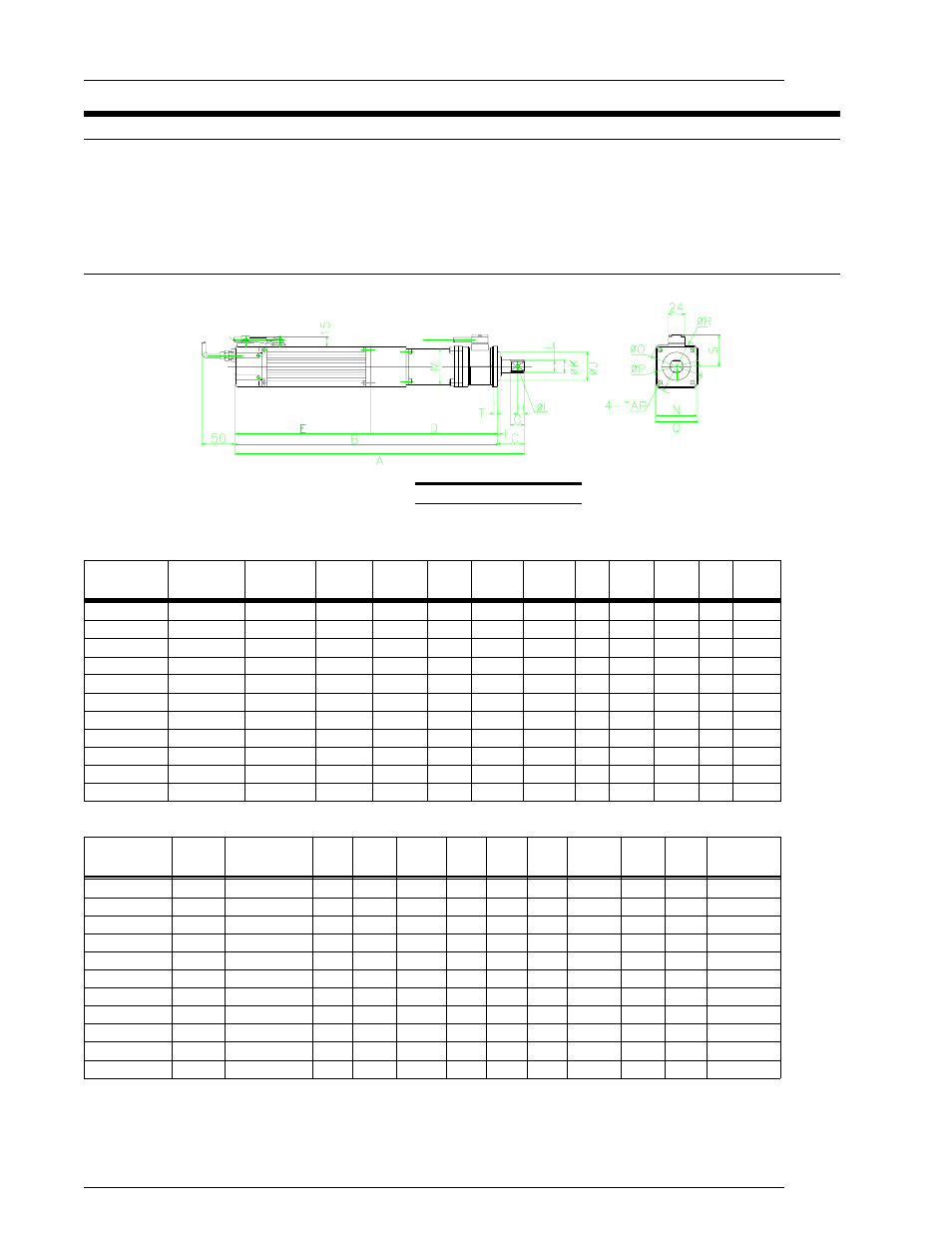
Nutrunner (Tool) Dimensions
Tool dimensions and mounting specifications are critical in determining the design of the powerhead
that will house the tool assemblies. Caution must be taken to ensure that the tool assemblies do not
come in contact with any other assembly. Failure to provide adequate clearance may result in
inaccuracies in the monitoring capability of the system or possibly damage to the tool assembly.
Torque capabilities of each tool assembly are specified to aid in determining tool requirements.
4.4.1 Straight Tool
FIG. 4-4-1 Straight Tool
Numbers shown in brackets are in inches. All others shown in millimeters as the standard.
62
6.5
15
30
6
255
310
50
565
615
110
50
502M4-S
52
5.5
13
25
5
202.5
228
40
430.5
470.5
150
30
302M3-S
42
5.5
10
20
4
202.5
210
40
412.5
452.5
220
20
202M3-S
42
5.5
10
20
4
202.5
168
40
370.5
410.5
315
15
152M3-S
42
5.5
10
20
4
202.5
189
40
391.5
431.5
395
13
132M3-S
42
4.5
8
16
4
202.5
180
40
382.5
422.5
500
8
801M3-S
42
4.5
8
16
4
202.5
145
40
347.5
387.5
790
6
601M3-S
42
4.5
8
16
4
147.5
180
40
327.5
367.5
500
4
401M2-S
32
3.5
5
12
4
140
159
30
299
329
250
4
401M1-S
32
3.5
5
12
4
140
159
30
299
329
500
2
201M1-S
32
3.5
5
12
4
140
159
30
299
329
500
1
101M1-S1
J
I
H
G
F
E
D
C
B
A
SPEED
(rpm)
TORQUE
(kgm)
DFT-
TYPE
13
15
56
110
80
M10
90
110
80
73
25.4 (1.00)
32
502M4-S
10
12
54
102
76
M8
87
102
76
73
19.0 (.748)
25
302M3-S
6
8
47
80
62
M8
68
80
62
54
15.8 (.622)
20
202M3-S
6
8
47
84
62
M6
68
84
62
54
15.8 (.622)
20
152M3-S
5.5
6
47
80
60
M6
68
80
60
54
15.8 (.622)
20
132M3-S
5
6
43
80
60
M6
62
74
54
51
12.7 (.500)
16
801M3-S
5
6
43
80
60
M6
62
74
54
51
12.7 (.500)
16
601M3-S
3.2
6
43
80
60
M6
62
74
54
51
12.7 (.500)
16
401M2-S
3
5
36
55
40
M4
46
55
40
38
9.5 (.374)
12
401M1-S
3
5
36
55
40
M4
46
55
40
38
9.5 (.374)
12
201M1-S
1.9
5
36
55
40
M4
46
55
40
38
9.5 (.374)
12
101M1-S1
WEIGHT
(kg)
T
S
R
Q
TAP
P
O
N
M
L
K
DFT-
TYPE
Chapter 4: System Setup and Wiring
Page 4-6