FEC AFC1200 User Manual
Page 26
)(& ,QF
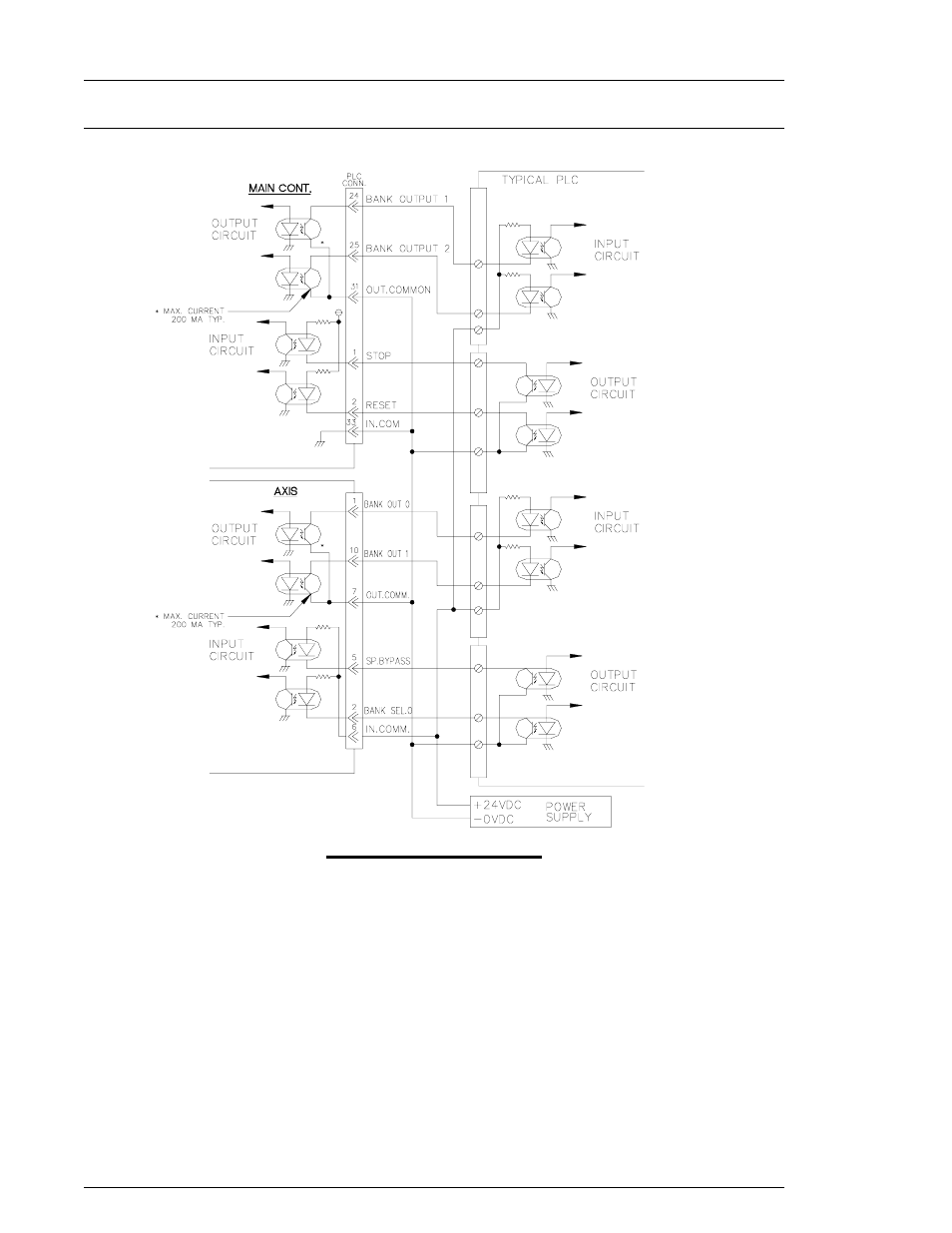
4.7.6 PLC Wiring Sample
FIG. 4-7-6 PLC Wiring Sample
All interface devices must accommodate active true low logic for correct operation with
AFC1200 inputs and outputs (I/O). Outputs are rated at +12~24 VDC, 200mA. When
activated, open collector sink outputs (normally high) pull the input device signal low
(0 VDC). Inputs are sourced (normally high) and activated when pulled low (0 VDC).
Located on the Multi2 PCB, Jumper JP2 is used to select internal or external input (source)
voltage. JP2-2 is an internal +5 VDC supply (normal mode), and JP2-1 is external +24 VDC
supply. If JP2-1 (external supply) is selected, then +12~24 VDC must be supplied at Pins 15
and 16 on the PLC2 connector.
CAUTION:
The PLC I/O wiring must be routed a minimum of 300 mm away from any
transient high voltage sources. Cable length must not exceed 50 feet.
DO NOT connect a positive DC voltage source to the input or output (0V)
commons on the PLC1 connector.
Chapter 4: System Setup and Wiring
Page 4-26