FEC AFC1200 User Manual
Page 24
)(& ,QF
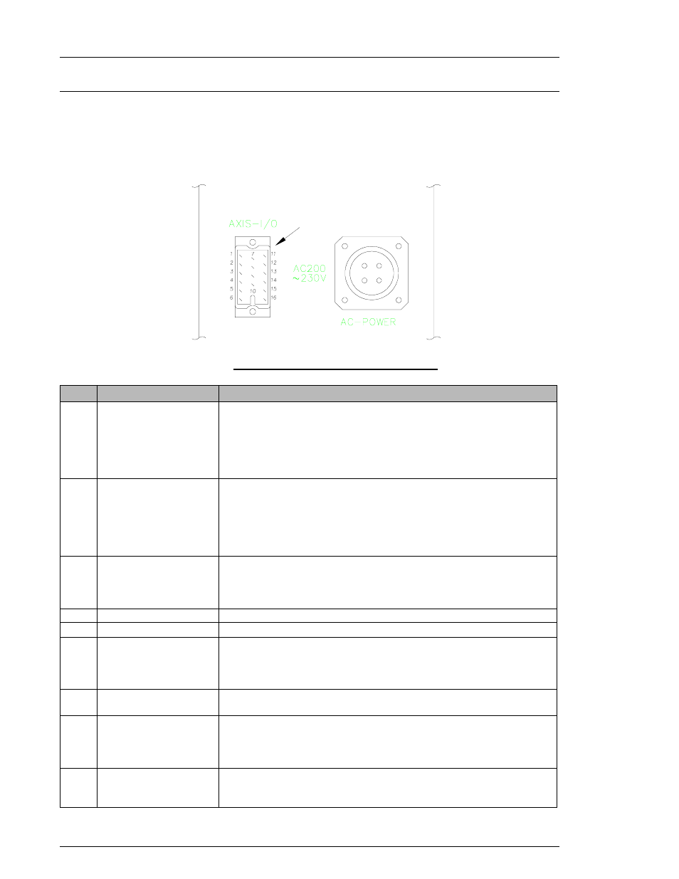
4.7.4 Description of Axis Unit I/O
Individual spindle PLC signals connect to each Axis Unit via the PLC connector located on the
front of the Axis Unit.
CAUTION:
The PLC I/O wiring must be routed a minimum of 300 mm away from any transient high
voltage sources. Cable length must not exceed 50 feet.
FIG. 4-7-4 Axis Unit I/O (PLC) Connector
Angle CW/CCW Output (Analog output 0 VDC / +5 VDC)
High (+5 VDC) = Clockwise Low (0 VDC) = Counterclockwise
This signal shows the direction of the tool rotation.
ANGLE CW/CCW
13
Analog Output Disable Input (Normally Open)
This signal will disable the analog output signals for the Axis Unit.
This allows all analog signals to be connected in parallel with only
one Unit's outputs enabled at a time.
ANALOG SIGNAL
MONITOR DISABLE
12
Common for Analog Signal Monitor Disable.
ANALOG SIGNAL
MONITOR COMMON
11
Bank Data Output Signals (Normally Open)
These output signals designate various fastening conditions and
results as determined by Bank Select 0 & 1 (Pins 3 & 2) inputs.
Refer to 4.7.5 Axis Bank Select Table.
BANK DATA 3
BANK DATA 2
BANK DATA 1
BANK DATA 0
8
9
10
1
Common for PLC Output (0 V).
OUT COMMON
7
Common for PLC Input (12~24 VDC).
IN COMMON
6
Spindle Bypass Input (Normal Open)
When active, all functions of this spindle are bypassed, and the
Bypass output is active. The ISA Main Unit will ignore Bypassed
spindles. Judgment will be made on enabled spindles only.
SPINDLE BYPASS
5
PLC Output Disable Input (Normally Open)
This signal is typically used to isolate Axis Unit outputs when Bank
Data 0~3 outputs are connected in parallel. A 24-spindle System
connected in series would require 96 outputs to the PLC, but
connected in parallel only four (4) outputs and 24 inputs are
needed.
DISABLE OUTPUTS
4
Bank Select Input Signals (Normally Open)
These two (2) inputs form a binary code that is used to define the
function/definition of outputs Bank Data 0~3 (Pins 1, 10, 9, & 8).
This allows up to 16 different output definitions with only four (4)
discrete outputs (four (4) Banks, four (4) available outputs per
Bank). Refer to 4.7.5 Axis Bank Select Table.
BANK SELECT 1
BANK SELECT 0
2
3
DESCRIPTION
SIGNAL NAME
Pin #
Chapter 4: System Setup and Wiring
Page 4-24