FEC AFC1200 User Manual
Page 5
)(& ,QF
4.3
Component Arrangement
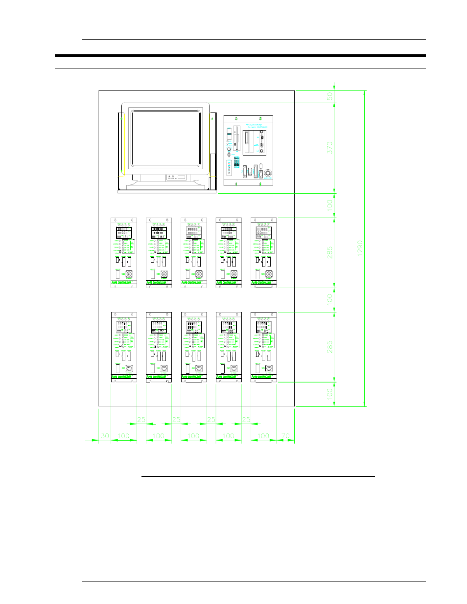
FIG. 4-3 Arrangement of System Components (Inside the Enclosure)
System components may be mounted in any desired configuration as long as the minimum clearance
requirements are not neglected. Communication bus ribbon cables can have a maximum length of 48
inches.
The ISA Main and Axis Unit mounting brackets are designed with slotted holes which require 8-32
screws for back panel mounting. These brackets may be reconfigured, if needed, for swing door
mounting.
When installing duct above or below the Units, allow adequate space for convenient removal and
installation of the Units without removal of the mounting screws.
Chapter 4: System Setup and Wiring
Page 4-5
See also other documents in the category FEC Accessories for electrical:
- AFC1500 (4 pages)
- AFC1500 (14 pages)
- AFC1500 (20 pages)
- AFC1500 (2 pages)
- AFC1500 (63 pages)
- AFC1500 (83 pages)
- AFC1500 (129 pages)
- AFC1500 (198 pages)
- AFC1200 (6 pages)
- AFC1200 (8 pages)
- AFC1200 (12 pages)
- AFC1200 (5 pages)
- AFC1200 (22 pages)
- AFC1200 (34 pages)
- AFC1200 (16 pages)
- AFC1200 (9 pages)
- AFC1200 (13 pages)
- AFC1200 (4 pages)
- AFC1200 (23 pages)
- AFC1200 (10 pages)
- AFC1200 (33 pages)
- AFC1200 (14 pages)
- AFC1200 (24 pages)
- AFC1200 (93 pages)
- AFC1200 (30 pages)
- AFC1200 (90 pages)
- AFC1150 (4 pages)
- AFC1150 (10 pages)
- AFC1150 (18 pages)
- AFC1150 (6 pages)
- AFC1100 (7 pages)
- AFC1100 (9 pages)
- AFC1100 (4 pages)
- AFC1100 (13 pages)
- AFC1100 (21 pages)
- AFC1100 (8 pages)
- AFC1100 (28 pages)
- AFC1100 (18 pages)
- MICRO NR (118 pages)
- FUSIONE-HS-2 (183 pages)
- DSP1500 (SAN3) (6 pages)
- DSP1500 (SAN3) (10 pages)
- DSP1500 (SAN3) (8 pages)
- DSP1500 (SAN3) (26 pages)