Emergi-Lite Preceptor Remote Capacity Series User Manual
Page 2
Preceptor Series – Remote Load Die Cast EXIT Series
Emergi-Lite
Tel: (888) 552-6467 ext. 547 or 255
Fax: (888) 867-1565
www.emergi-lite.com
07/04 750.1099 Rev. A
2/4
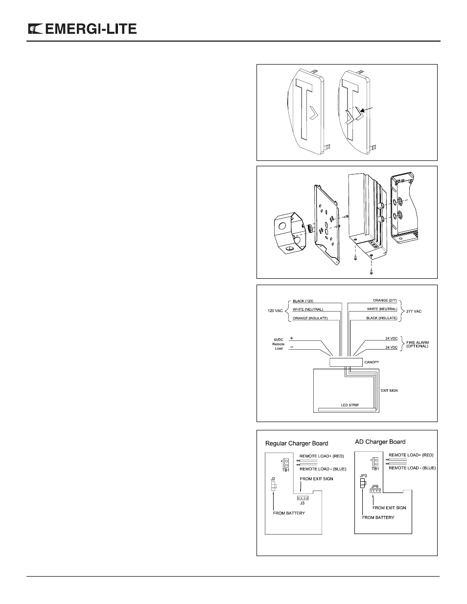
120 VAC — Connect the black wire (120 VAC) and white (neutral) to
the building utility. Insulate the orange wire.
277 VAC — Connect the orange (277 VAC) and white (neutral) to the
building utility. Insulate the black wire.
Push excess wires into junction box.
6. Remove exit from carton.
7. Remove exit door. Firmly grip top of door and pull forward. Push
against side of exit door to disengage hinge tab.
Note — On double-faced signs, only one side will open. Other side
must be detached by removing screws from inside of sign.
8. To knock out chevrons (see fig. 3), remove colored lens(es) by warp-
ing center of lens and pulling out from the securement clips. Support
door chevrons with two blocks of wood, strike chevron knockouts
from the inside with a hammer and screwdriver. To reinstall colored
lens(es), warp to slide under securement clips. Press securement
clips tightly onto lens. If sign is double-faced, repeat the procedure
for the second face.
9. Determine which two holes in the exit frame will be used for mount-
ing. Support area around knockouts by two blocks of wood, maxi-
mum one inch apart. Strike knockouts from the inside with a hammer
and screwdriver. Clear holes of burrs to allow proper fit with hex. nip-
ples.
10. Remove hexagonal nuts from hex. nipples.
11. Push hex. nipples, attached to canopy, through knockouts in exit
frame (see fig. 4). Fasten canopy to exit frame using large hexagonal
nuts. Thread nuts onto nipples and tighten.
12. Route the 4-pin harness from the EXIT sign into the canopy through
either nipple.
13. For regular charger board, connect the EXIT sign harness to the J3
terminal (see fig.6 A). For AD charger board, connect the EXIT sign
harness to the JP8 terminal (see fig.6 B).
14. Connect the remote load wires to the TB1 terminal block. Check for
correct polarity before connecting (see fig. 6). Do not exceed the
rated remote power of the equipment (check catalogue for details).
15. Connect the battery harness to J2, for regular charger board (see
fig.6 A) or to JP3, for AD charger board (see fig.6 B).
16. Mount EXIT sign and canopy assembly to canopy backplate by guid-
ing the notches on the canopy backplate into the slots of the canopy.
Secure with the two provided screws (see fig. 4).
17. Re-install exit door.
18. Energize AC. EXIT sign will illuminate. The Green "AC ON" indicator
will be ON continuously.
Figure 3
removing the chevrons
Figure 4
Figure 5
*Connect either 120 VAC or 277 VAC*
Figure 6
A
B