Emergi-Lite RS Series User Manual
Important safeguards, Read and follow all safety instructions, Save these
Emergi-Lite
Tel: (888) 552-6467 ext. 547 or 255
Fax: (888) 867-1565
www.emergi-lite.com
12/07 750.0144 Rev. D
RS Series - Emergency light unit
1/3
RS Series - Emergency light unit
6 and 12 volt Decorator Recessed
IMPORTANT SAFEGUARDS
When using electrical equipment, basic safety precautions should
always be followed including the following:
READ AND FOLLOW ALL SAFETY
INSTRUCTIONS
1. Do not use outdoors.
2. Do not let power supply cords touch hot surfaces.
3. Do not mount near gas or electric heaters.
4. Use caution when handling batteries. Avoid possible shorting.
5. Equipment should be mounted in locations and at heights where it
will not readily be subjected to tampering by unauthorized personnel.
6. The use of accessory equipment not recommended by the manufac-
turer may cause an unsafe condition.
7. Caution: If optional Halogen cycle lamp(s), symbol (H—), are used in
this equipment, to avoid shattering: do not operate lamp in excess of
rated voltage, protect lamp against abrasion and scratches and
against liquids when lamp is operating, dispose of lamp with care.
8. Halogen cycle lamps operate at high temperatures. Do not store or
place flammable materials near lamp.
9. Do not use this equipment for other than intended use.
10. All servicing should be performed by qualified service personnel.
SAVE THESE
INSTRUCTIONS
Installation Instructions
1. Turn off AC power.
2. Remove the four cover screws and retain. Set cover/electronics
assembly aside (see fig. 2).
Choose the proper mounting solution: wall mount, new construction
wood framing or suspended ceiling. Follow the proper mounting section
and continue the installation at step 3.
Wall mount
a. Remove appropriate knock out for AC supply.
b. Cut hole in sheet rock & frame.
c. Mount back box permanently into place by leaving the edge 3/8 of
an inch away from the sheet rock surface.
New construction wood framing
a. Determine the desired orientation between framing members.
Locate sides of the back box that will be at right angles to the
framing members. Mount the adjustment brackets to these sides
using the studs on the brackets and nuts. Do not tighten (see fig.
3)
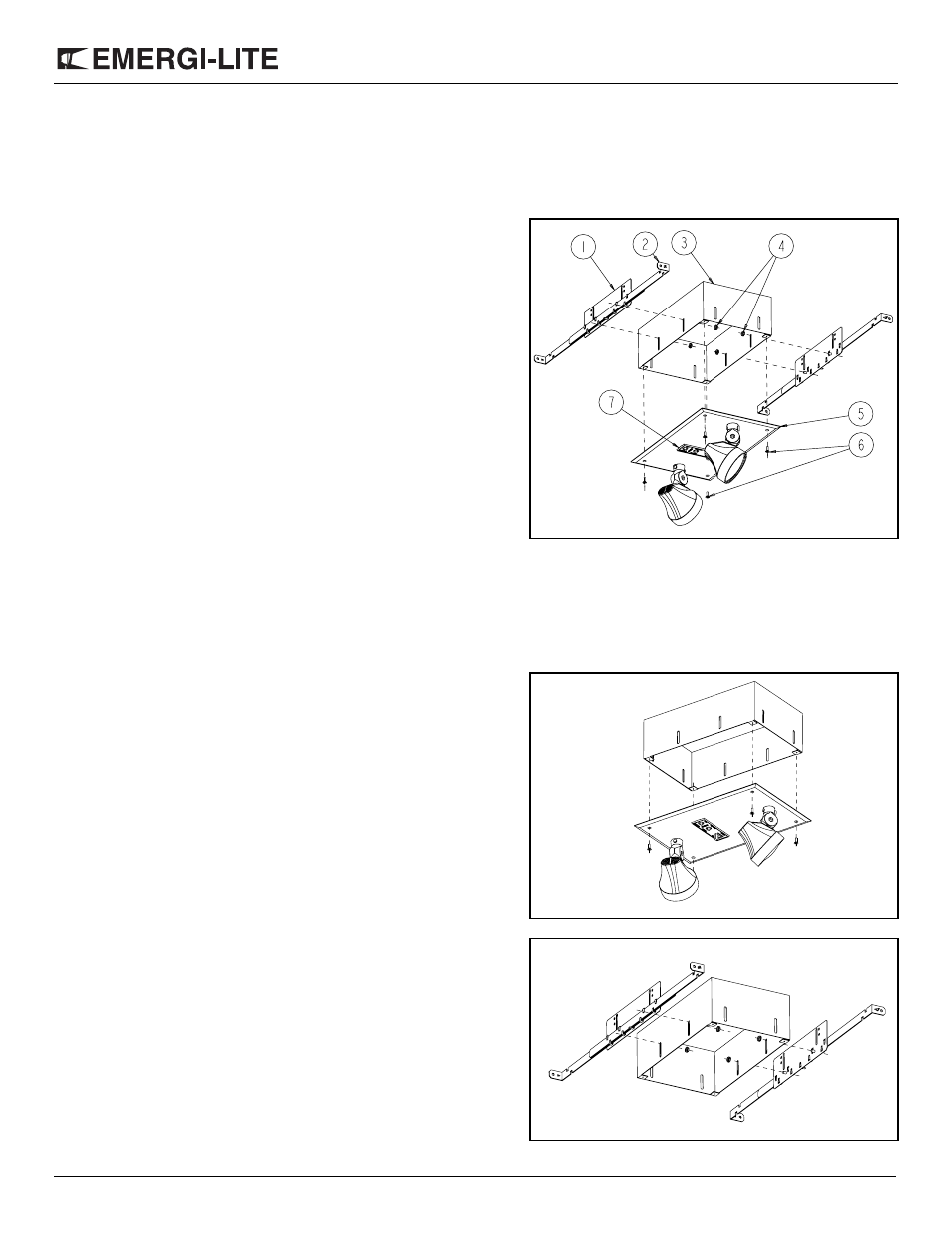
Figure 1
Part List
1.
Adjustment brackets (2)
2.
Hanger bars (4)
3.
Back Box
4.
Kep nuts (4 provided)
5.
Cover
6.
Cover screws (4 provided)
7.
Test switch and/or diagnos-
tics indicator
Figure 2
Figure 3